Industrial Gas Burner Controller
Background
Suppliers of industrial automation equipment are facing growing competition and have to adapt to changing market conditions. To do this, they need modern, competitive solutions that meet efficiency and safety requirements. In this project, Integra Sources was asked to design such a solution, namely a controller for industrial gas burners.

Request
Our customer develops and manufactures automation solutions as well as control and measuring equipment for industrial enterprises. The company’s products find use in various industries, including energy, agriculture, metallurgy, chemicals, petrochemicals, construction, and others.
The client contacted the Integra team to benefit from our expertise in developing complex electronics. Our task was to design a controller for 1- and 2-stage gas burners or low- and medium-power gas burners, similar in characteristics to equipment produced by leading market players. Gas and liquid-fuel burners are used in many industrial scenarios: for heating metals in smelting furnaces; for producing heat and steam in industrial boilers; for many processes in the chemical, oil and gas, glass, ceramics, and other industries.
Together with the client we built a partnership, where our team integrated with the customer's processes during firmware development for the device. This allowed the resources of both parties to be used as efficiently as possible.
The device is required to perform the following functions:
- To control the burner mechanisms via various relays. That included igniting and extinguishing the flame, adjusting the flame intensity, etc.
- To detect abnormal situations: absence of flame, absence of ignition spark, short circuits, and others.
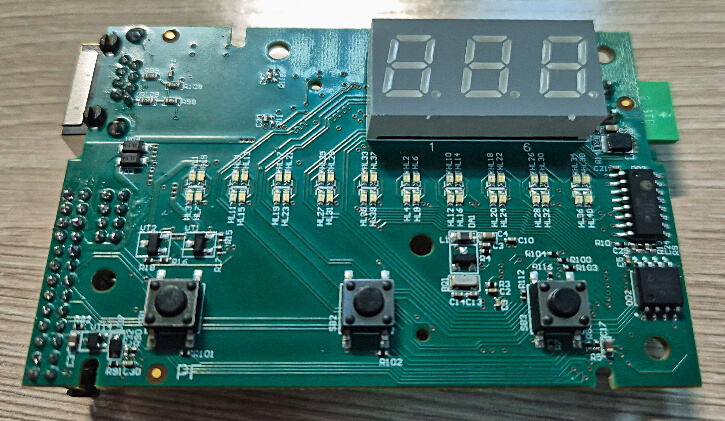
- To display information about the device’s operating modes on indicator elements (a row of 10 LEDs showing the flame ionization current and a seven-segment display).
- To allow for remote control through RS-485 and Ethernet interfaces.
- To connect to a PC via a USB port for configuration and data retrieval from the archive.
The team was assigned the following tasks:
- To design the hardware for the burner controller;
- To develop test firmware for verifying the product’s functions;
- After the project launch, the client also asked us to develop embedded software for the device.
Solution
The project had strict size requirements for the device. Therefore, we decided to design two smaller printed circuit boards so that they could be placed one above the other inside the enclosure. The upper board is responsible for operating the indicators, buttons, Ethernet, and RS-485 ports. The lower board houses high-current relays, the power supply, the current metering circuit, and blade connectors. This approach allowed all the required components to fit within a limited space.
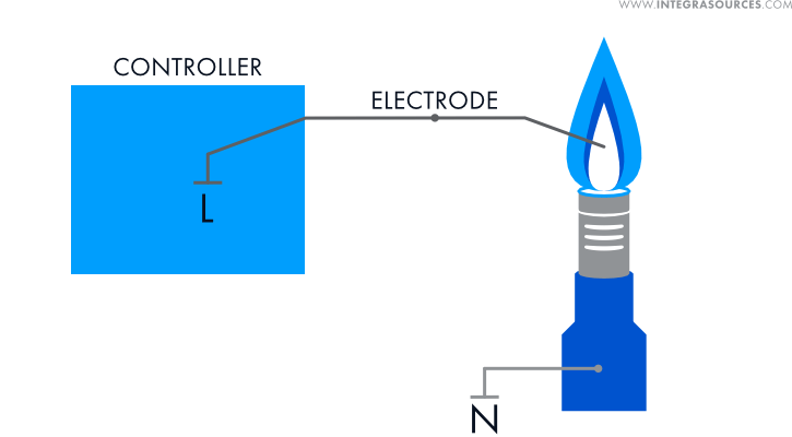
The main functions of the controller are to manage the connected equipment (gas/oil burner), detect the flame in the burner, and measure the flame intensity. To do this, the device measures the flame ionization current. When gas burns, it forms positive ions and free electrons, enabling the flame to conduct electric current. The absence of current indicates no flame. Current intensity is proportionate to the ionization intensity: the stronger the flame, the higher the current.

The flame also produces a rectifying action, which allows the controller to distinguish flame (that conducts direct current) from a short circuit between the flame ionization sensor and ground (which is alternating current).
The controller is also equipped with several external load control relays. They are used to send commands to the connected equipment: ignition transformer, valves, air compressors, etc. Many burner controllers from leading suppliers check the load only before launch, but the team made a valuable enhancement to the functionality of the device. The controller we designed provides continuous monitoring of external equipment in real time. If a load stops consuming current (turns off), the controller records this and reports an error. This significantly increases operational safety as operators can immediately take measures to prevent potentially dangerous situations.
The device has 3 communication interfaces. The USB port is used to connect it to a personal computer. This way, one can configure the controller and read data from its archive. The Ethernet and RS-485 ports allow for controlling the device remotely, which also contributes to the safe operation of the solution.
The controller is equipped with an LED bar that displays the flame intensity and a seven-segment indicator with three digits for displaying error codes and device operating parameters. The enclosure also has three buttons for switching parameters.

One of the team's key priorities was the safety of burner operation. Therefore, we developed a comprehensive diagnostic system capable of detecting and preventing a wide range of abnormal situations such as:
- No flame or electrode connection
- Ionization electrode to ground short circuit
- Ignition spark hitting the ionization electrode, etc.
Each scenario was carefully analyzed, taking into account the real operating conditions of industrial equipment.
Special mention should be made of relay sticking protection. If any relay does not turn on or off (because of contacts sticking), the microcontroller generates a warning signal for the upper-level software.
In addition, the working contacts of the secondary relays are connected in series to the main relay. To keep the main relay in the working position, the microcontroller supplies an active signal level to it. This is the only way for the secondary relays to turn on the outputs (X7, X4, X5, X9). If the microcontroller fails, the main relay will switch to the default state and the connection to the secondary relays will be terminated. This prevents uncontrolled behavior of the connected equipment if the microcontroller fails.

Major Issues Resolved
Hardware Components Limitation
The customer’s company owns a manufacturing facility. In order not to disrupt its well-established supply chains, we did our best to only use the components from the client’s suppliers. We also chose an APM32F4xx family microcontroller to ensure that the software is compatible with the products developed by the company previously.
Layout Density
The size requirements for the device presented a serious engineering challenge: we had to place many components, including large relays, in a limited space. The solution was to develop two 4-layer printed circuit boards with optimized topology. This way, we were able not only to meet the dimensional requirements but also to ensure optimal thermal distribution, which is critical for the reliable operation of the device.
Working with the Customer's Framework
Our part of firmware development involved creating drivers, i.e., a low-level software layer responsible for interacting with specific hardware nodes. Each such driver has an abstraction layer (container) that interacts with the high-level software responsible for the business logic (device’s functions). The container system is designed to speed up development. Therefore, the team was required to use the customer's proprietary framework.
Since we were not familiar with the tool, we had to spend some time training our developers. In addition, the team had to manually create special description files for the correct interaction of business logic with containers. This task required a lot of attention.
Creating firmware with the customer's framework allowed the software to integrate well with the customer's existing solutions. This also makes further maintenance and software updates easier. Therefore, the team quickly mastered this tool before moving on to designing the firmware.
While working on it, we also improved the code created by the customer's developers. In particular, we significantly modified the ADC (analog-to-digital converter) container, which noticeably increased its performance. The original code, developed for other products, took measurements only 1,000 times per second. However, the burner controller project required a much higher speed. The team was able to raise the parameter to approximately 80,000 measurements per second.
Current Measurement Technique
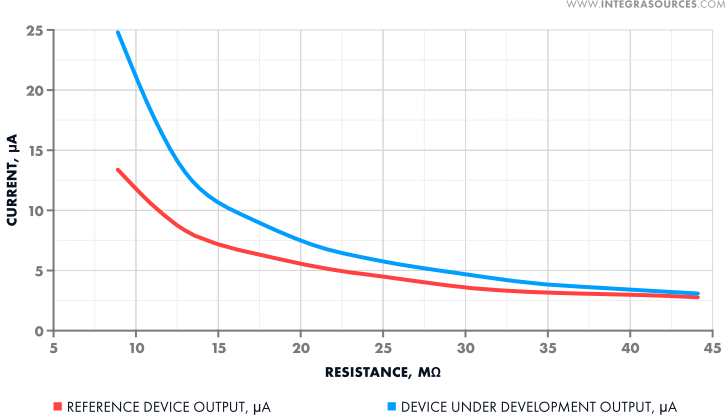
A lot of effort was required to analyze how the reference device measures the flame ionization current. It turned out that due to the differences in the internal impedances of our controller and the reference device, they show different current values. The following picture shows this difference:

However, this difference does not affect the quality of flame control.
In addition, the signal in the reference device is converted by hardware, while we implemented software processing of ionization current data. This fundamental difference provides exceptional flexibility of adjustment: the operating parameters can be adapted to specific operating conditions without changing the hardware. This approach allows for prompt improvements in processing algorithms and expansion of the device's functionality through software updates.
Scope of Work
- Printed circuit board design and testing;
- Test firmware development;
- Embedded software development.
Technologies
- APM32F407VGT6 as MCU.
- Altium Designer for schematics and PCB design.
- C/C++ and the customer's container platform for embedded software development.
- C/C++ and CMake for test firmware.
Result
Integra Sources developed a controller for 1- and 2-stage low- and medium-power gas burners. The device’s characteristics are similar to those of the equipment from the leading manufacturers, but it is distinguished by increased safety. Now the customer is actively preparing to release the product.
The solution allowed the customer to:
- Offer an industrial burner controller that can compete with popular solutions from the leading manufacturers of industrial equipment.
- Manufacture the device using components that are available from the company's current suppliers.
- Reduce the strain on the company’s own R&D team by delegating the project to Integra Sources
You might also like...

Firmware Development for Augmented Reality Glasses
The team improved the customer’s firmware for augmented reality glasses by developing drivers for the displays, accelerometer, and gyroscope of the device. 
LEARN MORE 

Software for EEG System
The Integra Sources team developed energy-efficient embedded software and an SDK for a medical EEG system. We delivered robust data transfer and storage, implemented multitasking on FreeRTOS, and improved connection security. 
LEARN MORE 


