This website uses cookies so that we can provide you with the best user experience possible. Cookie information is stored in your browser and performs functions such as recognising you when you return to our website and helping our team to understand which sections of the website you find most interesting and useful.
Battery Management System (BMS): Effective Ways to Measure State-of-Charge and State-of-Health


Andrey Solovev
Chief Technology Officer, PhD in Physics and Mathematics

Anna Petrova
Writer With Expertise in Covering Electronics Design Topics
- Bear the Battery in Mind
- SOC and SOH: What Are They All About?
- Calculating Your Battery’s State-of-Charge
- Open Circuit Voltage (OCV) Method
- Coulomb counting (Current integration)
- Kalman filtering
- Alternative SOC estimators
- Calculating Your Battery’s State-of-Health
- Internal resistance measurement
- Internal impedance measurement
- Counting charge/discharge cycles
- SOC estimators working for SOH
- Kalman Filter Use Case in Estimating the SOC
- Conclusion
The major task of a battery management system (BMS) is to provide security and longevity of the battery. This can be done through continuous monitoring and control of the battery’s state-of-charge (SOC) and state-of-health (SOH). In this post, we’ll highlight the core BMS functions and tell you about the SOC and SOH estimation techniques through the lens of our personal experience in large-scale projects, such as battery energy storage systems (BESSs). That said, the solutions we’re going to cover here can be relevant to any system that operates on a rechargeable battery and might need a BMS.
- Bear the Battery in Mind
- SOC and SOH: What Are They All About?
- Calculating Your Battery’s State-of-Charge
- Open Circuit Voltage (OCV) Method
- Coulomb counting (Current integration)
- Kalman filtering
- Alternative SOC estimators
- Calculating Your Battery’s State-of-Health
- Internal resistance measurement
- Internal impedance measurement
- Counting charge/discharge cycles
- SOC estimators working for SOH
- Kalman Filter Use Case in Estimating the SOC
- Conclusion
Bear the Battery in Mind
Rechargeable batteries can power a variety of systems and solutions. Most of them require a BMS to ensure the safe and long-lasting performance of the battery, including through the correct SOC and SOH calculations.
From now on we’re going to talk about SOC and SOH estimation methods that we used during the development of BESS projects. However, the same methods can work for your system too—no matter how large and complex the BMS is.
A BESS is an electrochemical energy storage solution with a rechargeable battery lying at the core. The system can either store or feed power as needed by charging and discharging its battery at the right time. Previously, we enlarged upon battery energy storage solutions, their applications, and nuances that are worth your attention as you choose to buy or build a BESS on your own.
A battery management system is both a supervisor and a caretaker of the battery—the system monitors and controls the condition of the battery cells and protects them from any potential threat. Creating a BMS is a multifaceted process—you need to design a set of subsystems at both hardware and software levels. Earlier, we elaborated on BMS functionality and its software implementations.
The first thing you need to consider when developing a BMS is the battery technology your BESS is going to use. Battery energy storage solutions can have the following battery cells configurations:
- Lithium nickel manganese cobalt oxide
- Lead-acid
- Nickel-cadmium
- Sodium-sulfur
- Zinc-bromine
Battery chemistry has a wider spectrum of combinations, and each type has its features and characteristics. The best thing is to choose a battery that fully meets your BESS specifications. For example, the system’s operating conditions mean a lot because battery chemistries have varying thermal tolerance. Thus, lithium-ion batteries are not resistant to extreme temperatures—they can operate properly in the range between 10oC and 40oC. Here, you can read about different battery technologies along with their merits and flaws.
Rechargeable batteries can be charged and discharged multiple times because of the reversible electrochemical reactions that can repeatedly restore the electric charge of a battery. There are certain recommendations on how to charge and discharge different battery types.
For example, it is best to recharge lithium-ion batteries even after a minor discharge—say 30% of capacity—and avoid complete energy drain or overdischarge that would destroy the battery. Nickel-metal hydride (Ni-MH) batteries can be safely recharged irrespective of the capacity level, but regular recharging is a must for them if stored or left unused for a long time. Lead-acid batteries must be stored at full charge, otherwise, they would become sulfated and lose their capacity.
Charging/discharging requirements include voltage, current, and temperature limits, and going beyond these limits may lead to battery damage. In one of our BESS projects, we implemented custom battery management algorithms that control the range of the above parameters. The BMS stops charging the batteries automatically and alerts users to the overrange.
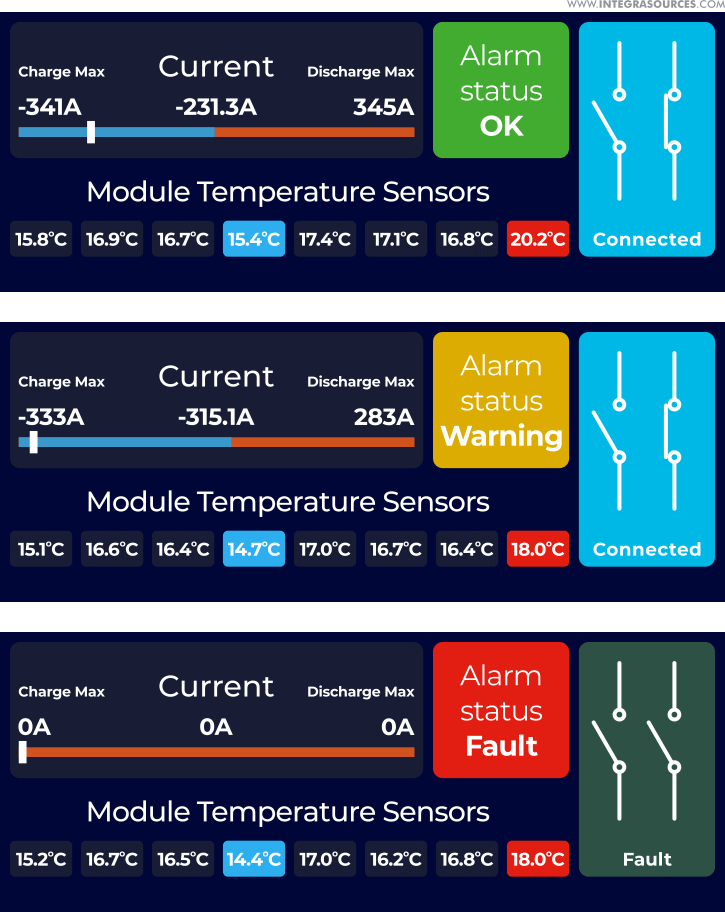
By calculating the state-of-charge, a BMS takes charging and discharging under control and thus protects the battery from premature capacity loss and prolongs its lifetime. Estimating the state-of-health is another important BMS function that helps users enhance the performance of their batteries. This article will focus on these two essential battery characteristics and their evaluations that give BMS designers a real headache. Having experienced that first-hand, we’re happy to share the insights with you.
We’ll take a close-up look at the SOC and SOH estimations for lithium-ion batteries—they prevail over other technologies on the battery market and find use in most modern BESSs. According to the Research and Markets report, the global lithium-ion battery market is valued at US$43.16 billion in 2023 and is expected to reach US$97.92 billion by 2030, with a CAGR of 12.4%.
Li-ion batteries have high capacity and energy density, low maintenance, a long life span, a high charging rate, and a low self-discharge rate. In addition, with less weight and size, lithium-ion batteries provide more energy than other chemical batteries. All of the above advantages make the li-ion battery a tempting solution for manufacturers, engineers, and end users of battery storage systems.
SOC and SOH: What Are They All About?
The SOC and SOH are the key metrics that describe the performance of the battery and help predict its future behavior. The state-of-charge shows the amount of electric charge left in the battery. It’s expressed as a percentage that ranges from 0% to 100% depending on the charge level. By looking at the state-of-charge indicator, a user knows the resources and understands when the battery needs to be recharged.
The SOC is closely tied to the battery’s capacity and can also be determined as the ratio of the remaining capacity to the rated or maximum capacity specified by the manufacturer.

As time passes, every battery ages and degrades, as a result, the SOH goes below its initial level. Batteries with poor SOH discharge much faster than “healthier” batteries. This is the consequence of the decline in the rated capacity—an inevitable process that occurs over time. All this can serve as the evaluation criteria for finding out the SOH by battery management systems.
The accurate state-of-health battery estimation can give early warning of deterioration and the need for battery replacement. Once you know the SOH, you gain access to useful information regarding the performance of your battery and the entire energy storage system, including their efficiency and reliability.
Unlike with voltage or temperature, no special gauge could measure the battery state-of-health or state-of-charge. Neither SOH nor SOC has equivalents among physical quantities. You’ll have to consider a whole range of factors and parameters to assess these states most accurately. Thus, calculating the SOH can rely on:
- Age
- Cycle life (number of charge/discharge cycles)
- Capacity
- Internal resistance
- Energy throughput
- Temperature
- Self-discharge rate
- Voltage
When evaluating the SOC, you can refer to the following parameters:
- Battery chemistry
- Voltage
- Current
- Capacity
- Impedance
- Charging/discharging rate
- Temperature
Calculating the state-of-health and state-of-charge is a tough task. No simple and clear formula can assist developers of a battery BMS in identifying these characteristics. However, the internet has no lack of scientific studies and technical articles on SOC and SOH estimation methods. And many of them are claimed to be trusted and precise. Having tried different measuring techniques in real-world projects, we can tell you which of them work for a lithium-ion battery management system.
Calculating Your Battery’s State-of-Charge
Different practices could help you determine the level of your battery SOC. These practices involve direct measurements, indirect calculations, predictive techniques, and other technologies. Let’s go through the most popular methods available for use in the majority of battery management systems.
Open Circuit Voltage (OCV) Method
This method rests on the variation in the battery’s remaining capacity or SOC to the open-circuit voltage—voltage with the disconnected current load. The stronger the dependence between voltage and SOC, the higher level of measuring accuracy you can achieve. The relationship between these parameters is reflected in a look-up table as the discharge curve. Manufacturers can provide such a table in battery datasheets or you can create it yourself by experimental measurements.
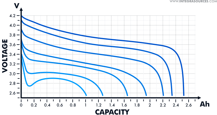
Although it varies with the battery chemistry, the dependence between voltage and SOC can be quite clear and the margin of error in the OCV method can be low enough. Nevertheless, this method is rarely applied in the real world. To use it, you need to cut off the current feed completely and give your battery a rest for some time—2 or 3 hours at the very minimum and 8+ hours in the ideal case. And only after all chemical reactions subside, you can gauge the battery’s voltage.
That means the OCV technique cannot measure the SOC of a battery while in operation unless the power consumption is very low and we’re talking about microamps. When your BESS or another battery-powered system is at work, it needs a constant electric power supply, and the current load can alter during operation. After a while, you’ll have to charge the battery, and that makes the OCV method an impossible task.
The open circuit voltage technique is well suited to determine the initial SOC battery characteristic. For example, you can use it to calculate the state-of-charge after extended storage of a battery or if your system was powered off for a time. After measuring the OCV, you can find out the initial SOC from the voltage-capacity chart.
Calculating the state-of-charge with the OCV method is not a good fit for lithium-based batteries that have a rather flat discharge curve. The voltage value of Li-ion cells may not fluctuate through much of the capacity range, especially at some temperatures. That’s why we always combine the OCV technique with other measurement practices for the SOC estimation in lithium battery management systems.


Coulomb counting (Current integration)
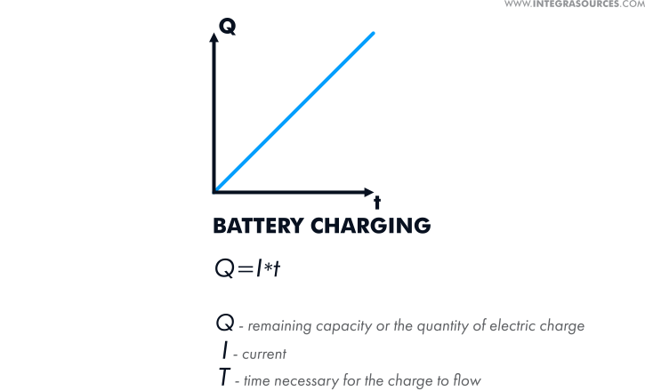
As the name suggests, this method is aimed at calculating coulombs or the quantity of electric charge, which is derived from current multiplied by the time necessary for the charge to flow. To measure the remaining capacity or SOC of a battery, you can add coulombs to the initial capacity in case of charging or take them away when you discharge the battery.
Current integration is a widespread method, but its accuracy depends on some factors. First off, you should know the correct measure of the initial SOC that serves as a reference point. You can get this by fully charging or discharging a battery. So if you want to use this technique, you need to allow for regular resetting of the battery SOC to 100% in your BMS design.
Another important condition for the accurate state-of-charge estimation with coulomb counting is the correct current measurement. You can achieve this by increasing the amplitude and time resolution of an analog-to-digital converter (ADC) in your current sensor. However, this can add to the sensor’s cost, so in most cases, BMS designers use inexpensive ADCs with 14- and 16-bit resolution and average measured data afterwards. Then, engineers process data by applying more advanced estimators, such as Kalman filtering or neural networks.
If you’re able to provide the conditions necessary for the efficient use of the current integration method, you can reach high accuracy in your SOC calculation. But this practice will not be reliable if you cannot regularly charge or discharge the battery to the full or if the current value is incorrect.
Coulomb counting is a widespread method that can help you reach high accuracy in the SOC calculation provided that you’re able to fully charge or discharge the battery and correctly measure the current.
Kalman filtering
This method banks on the measurements and analysis of the battery’s input and output data, such as current, voltage, temperature, internal resistance, and other parameters. Based on this data, you can use the Kalman filtering algorithm to build an electrical model of a battery, simulate its behavior along with operating conditions, and estimate the state-of-charge.
This method consists of two major steps. For starters, you enter the input data into the model and represent the physical processes running in a battery as mathematical equations. Thus, you predict the behavior of the battery and its output data by drawing on theoretical calculations.
In the second step, you measure the actual battery parameters, such as voltage and current, and compare them with the predicted values. After that, the algorithm filters or corrects the model to reduce any possible deviations. Kalman filter can take the measurements every second throughout the entire discharge or charge cycle of a battery and predict the SOC at each iteration, every time minimizing the margin of error.
Kalman filter is one of the most high-end and precise estimators used by modern battery management systems. To apply this practice, you don’t need to know the whole history of battery charging and discharging. You can only draw on the previous iteration to calculate the current battery state. The reliability of this method directly depends on the accuracy of the electrical model, including mathematical equations and the parameters you choose for these equations.
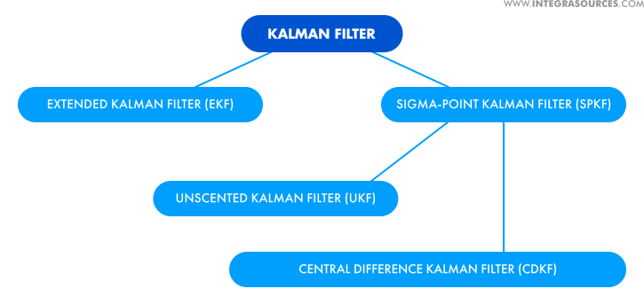
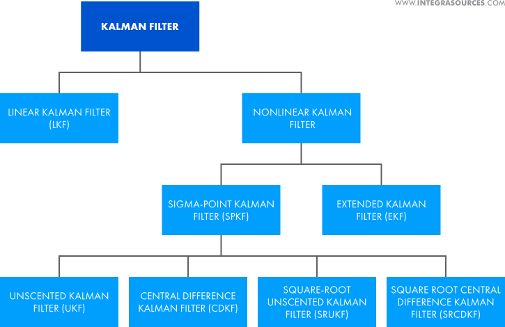
The classic Kalman filter algorithm works for systems described by linear ordinary differential equations (ODEs). For non-linear systems, you can use an extended Kalman filter (EKF) that approximates non-linearity using the first-order partial derivatives. This is an upgraded version of the algorithm that needs hardware with a higher level of performance.
The unscented Kalman filter (UKF) and central difference Kalman filter (CDKF) are the types of a sigma-point Kalman filter (SPKF), which is another modification having higher accuracy compared to EKF. For SPKF, you solve equations for a set of points offset by sigma from the initial point.
Kalman filter is one of the most precise SOC estimators used by modern battery management systems. Building an accurate battery model is key to the reliability of this method.
Alternative SOC estimators
There are a host of other techniques that can estimate the SOC of battery cells. Some of them have already been put into practice, the others are still in the research stage or exist as concepts. When investigating the SOC determination solutions, you can come across the following methods:
- Terminal voltage method. This method consists in measuring the terminal voltage of a battery that decreases during discharge. The SOC is calculated based on the proportional relationships between the electromotive force (EMF) of a battery, its terminal voltage, and the state-of-charge. There can be a serious error in the calculations due to a sharp drop of the terminal voltage at the end of discharge.
- Impedance method. This builds upon the measurements of a battery’s internal impedance that changes throughout charge and discharge cycles. The main challenges here are measuring impedance during the battery’s operation and obtaining correct data with allowances made for the temperature.
- Neural networks. A neural network can estimate the SOC by learning from large amounts of a battery’s input data, such as voltage, current, and temperature, and reproducing the non-linear relationships between these parameters.
- Fuzzy logic. To build a fuzzy logic model, you can use any battery data available to you even if it’s abstract and approximate. After analyzing the data, the model can determine battery characteristics, including the state-of-charge. The key requirement of both fuzzy logic and neural networks is the high performance of a microcontroller.
- Ultrasonic detection. This method lies in estimating the SOC using ultrasonic guided wave technology. Owing to its sensitivity, wave signals can help understand the battery structure and thus evaluate its capacity and overall condition. Implementing this practice requires significant investments of time and effort.
The application of a single SOC estimation approach is rarely found in present-day battery management systems. To improve your calculations, you can put different techniques together using so-called hybrid methods. For example, combined with fuzzy logic or Kalman filtering, coulomb counting can better measure accuracy than the current integration method alone.
Present-day battery management systems rarely apply a single SOC estimation method. Putting different techniques together can improve your calculations and increase measuring accuracy.
Calculating Your Battery’s State-of-Health
While the SOC can be aligned with the electric charge in a battery, the SOH is a more abstract characteristic associated with the battery’s capacity, age, and wear level. Even though you cannot measure the SOH battery parameter directly, you can calculate it through the measurements of related physical quantities. Let’s see how that is possible.
Internal resistance measurement
Internal resistance can be a distinct marker of the SOH that is inversely related to this parameter—the higher the battery internal resistance, the lower the state-of-health. Internal resistance can be calculated through the measurements of open circuit voltage and voltage with the connected current load. The difference between these two values will show the voltage drop. Then, you can calculate the internal resistance using Ohm’s law.

However, calculating the battery internal resistance this way takes time as you can only measure the OCV when the battery is at rest. Alternatively, you can calculate the internal resistance through Joule’s law by measuring the energy generated by the battery during operation. Or you can get the resistance value from the battery’s impedance using Electrochemical Impedance Spectroscopy (EIS).
Internal impedance measurement
As a battery degrades, its internal impedance increases, just like resistance. So you can also use the impedance measurement to estimate the state-of-health. As said above, the battery impedance can be measured by the EIS method that applies alternating current (AC) at different frequencies and identifies the impedance as a function of the frequency.
This technique enables engineers to calculate the internal impedance with high accuracy and thus precisely estimate the degradation level and SOH of a battery. That said, EIS is a complex solution that cannot meet the requirements of every BMS and may not match the operating conditions of a battery.
Counting charge/discharge cycles
There is a relationship between the state-of-health of Li-ion batteries and their cycle life. So calculating the remaining number of charge/discharge cycles can become the simplest and most available SOH estimator for them. In this case, the cycle life claimed by the battery manufacturer can serve as a reference point, and to count the number of cycles, you need to charge the battery to the full.
Despite the simplicity of this practice, it can hardly provide a high level of accuracy as some significant factors, such as voltage and current, could influence the battery’s state. This method does not make allowance for these factors along with the operating conditions of a battery.
You can calculate the battery SOH by counting the remaining number of charge/discharge cycles or through the measurements of related physical quantities, such as internal resistance and impedance.
SOC estimators working for SOH
The well-known techniques used for measuring the battery state-of-charge can just as well work for the SOH estimation. These include:
- Coulomb counting. The decrease in the state-of-health and the loss of rated capacity occur simultaneously in a battery. Thus, you can find out the SOH once you know the rate at which the capacity fades over time. The coulomb counting method is here at your service.
- Kalman filtering. The Kalman filter can lean on a variety of battery parameters, including internal resistance, which is essential for SOH estimation. The algorithm can track the behavior of a battery in real-time and predict its wear and aging.
- Neural networks. Neural networks can process both linear and non-linear data. By analyzing battery internal parameters, neural networks can estimate the SOH under various conditions.
- Fuzzy logic. Fuzzy logic models can use internal resistance, impedance, and other parameters as input data to evaluate the battery SOH. To apply the fuzzy logic method, you don’t necessarily need complete and comprehensive data about your battery.
- Ultrasonic detection. Monitoring of lithium-ion batteries using ultrasonic guided waves can be used both to assess the SoC and the SoH. There is a correlation between directional waves and battery SoC/SoH. Changes in the amplitude or duration of waveguide signals are associated with battery aging.
Like with the SOC estimation, the SOH is normally defined by blending several measuring practices. This approach allows BMS developers to view the battery from many different perspectives and determine its state with high accuracy. For example, you can achieve greater results by integrating the coulomb counting with neural networks or combining internal resistance and impedance measurements with fuzzy logic.
Also, you should bear in mind that some SOH or SOC estimation methods are not suitable for certain applications. For example, to extend the battery life in electric vehicles (EVs), it is strongly recommended not to fully charge or discharge the battery. That is why the cycle calculation and coulomb counting techniques do not fit EV battery SOH evaluation.
In the next part of this article, we’ll share hands-on experience in measuring the state-of-charge of batteries installed in an industrial battery energy storage solution. We opted for Kalman filtering as a basic method for this project, supporting it with additional estimation techniques.
The SOH is normally defined through the blending of several measuring practices. This allows you to view the battery from different perspectives and determine its state with high accuracy.
Kalman Filter Use Case in Estimating the SOC
As part of a complex BESS project, we were supposed to design hardware and software BMS solutions, including estimation algorithms to measure the battery SOC. To complete this task, we tried different options and finally chose the central difference Kalman filter as one of the most advanced, precise, and high-performance methods.
As with any Kalman filter, to apply the CDKF method, you need to build a mathematical model using the battery parameters, such as OCV, capacity, internal resistance, hysteresis coefficients, and others. The accuracy of the model and parameter matching will directly affect the efficiency of the algorithm.
In this project, we used an equivalent-circuit model—a simple and reliable solution found in the majority of present-day battery management systems. The circuit model simulates the behavior and internal processes of a battery cell. The final model we created for the project is as follows:

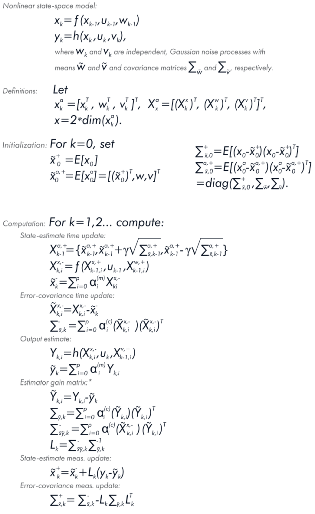
The next stage was building the Kalman filter equation, in which:
- x is the battery SOC consisting of capacity, OCV, internal resistance, hysteresis, and other parameters;
- f is part of the battery’s model or state equation that calculates the present state from the previous one based on the input data (temperature and current);
- y is the theoretical output data (voltage) under the battery SOC (x) and input data (temperature and current);
- h is part of the battery’s model or output equation that calculates theoretical output data from the present state and input data.
In light of the above, we computed the Kalman gain matrix (L) and based on that, adjusted the battery’s model—updated the state-estimate and error-covariance measurements.

Then, we wrote the equation for the battery model, in which the SOC rate of change (ż) with time becomes proportional to the input current multiplied by the charge efficiency (η) and divided by the capacity (Q):

We solved this differential equation as follows: the SOC (z) at time t (z(t)) is equal to the SOC at the initial time t0 minus (or plus depending on the current direction) the electric charge that flows in or out during this time divided by Q. In other words, this is the equation of integration (accumulation) of the current charged or discharged for some time.

We can also write this equation in discrete form, describing the continuous time flow as discrete steps (Δ):

If we consider only internal resistance in the model, the output voltage will be equal to the OCV minus resistance voltage drop (R0) at the present current (Ohm’s law). Thus, the model will be as follows:

The same equation in the discrete form:

If we add a resistor-capacitor (RC) circuit to the model, the voltage will drop at the resistor R1, and the equation will look like this:

To calculate the iR1, we also add it to the model as part of the SOC:

These differential equations can be solved as follows:

To identify the voltage hysteresis, we wrote the following model equations:

The above equation shows the instantaneous hysteresis (M0S[k]). It is abrupt and results from the change in the direction of the current flow. M0 is a coefficient and S[k] is the current direction. The continuous hysteresis grows exponentially and looks like this:

We put the instantaneous hysteresis and continuous hysteresis together to calculate the voltage hysteresis in the battery model.
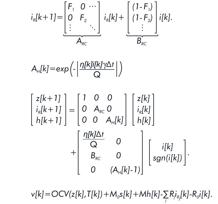
Finally, we received the following battery model equation:
Conclusion
A BMS takes full responsibility for the long and happy life of a rechargeable battery and consequently ensures the efficiency and reliability of the battery energy storage system. When building a BMS, you should heed the battery’s chemistry, parameters, and operating environment. You can effectively monitor and control your battery, keeping it inside the safe area with all this in mind.
The state-of-charge and state-of-health are vital characteristics that clearly show the condition of a battery and help users prolong its life span, predict future behavior, and replace the battery in good time. The SOC and SOH cannot be measured directly like physical quantities of a battery, such as current and voltage. Yet, there is a diversity of practices used to calculate the battery’s charge and health status.
The SOC and SOH estimation methods depend on the battery system’s application and vary in complexity, availability, and level of accuracy. However, both customers and developers favor the simplicity, feasibility, and cost-efficiency of measuring techniques. So if the method is expensive and hard to implement, it will hardly be chosen despite its high accuracy. The best way to achieve maximum accuracy at minimum expense is to use a combination of estimators.
The best way to achieve maximum accuracy at minimum expense is to use a combination of estimators.
We at Integra Sources can give you a hand with the choice of suitable methods that will meet your battery and system requirements. With our deep expertise in BMS design, we can develop electronics and write firmware for battery management systems with varying functionality. Our engineers have vast experience in creating robust algorithms that calculate the battery’s state-of-charge, state-of-health, state-of-energy, and state-of-power. In addition, we implement cell balancing and design BMS monitoring software, including dashboards and human-machine interfaces (HMIs).
To be up to speed on battery energy storage solutions, you can read our article series telling about battery management software, BMS security systems, types, applications, and peculiarities of ready-made vs custom BESSs. Or you can reach out to us and get all your questions answered.
Share this article


Related
materials


Battery Management System Development
Integra Sources reviewed the hardware and software of the battery management system. We provided PCB, firmware, app, and server development.
LEARN MORE
LEARN MORE
How to Avoid Battery Hazards: BMS Safety & Security Solutions
A BMS can make a battery feel safe and secure. Here’s how this system protects it from potential hazards.
LEARN MORE
LEARN MORE

State of Charge and State of Health in Infographics
We've prepared a cool infographic for our SOC and SOH article. Read the previous article and look at this post.
LEARN MORE
LEARN MORE


