This website uses cookies so that we can provide you with the best user experience possible. Cookie information is stored in your browser and performs functions such as recognising you when you return to our website and helping our team to understand which sections of the website you find most interesting and useful.
Battery Management System Development
A Battery Management System is an electronic system responsible for the correct and safe battery operation.
Batteries are used in numerous electronic devices, from toys, smartphones, and small appliances to electric vehicles, life support systems, and energy storage systems. Accordingly, BMS finds applications in various fields and has different functionalities.
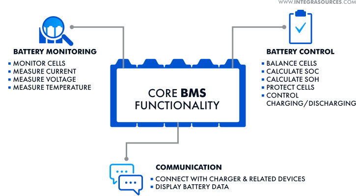
BMS consists of microcontroller-based hardware and embedded software. BMS performs a wide range of functions, such as
- measurement and control of current and voltage at the input/output;
- supervision of critical parameters;
- battery environmental control;
- battery data calculation, storage, and transmission to a user or higher level system.
The BMS can evaluate the battery condition based on physical quantities, chemical composition, and operating conditions. These characteristics include
- the State of Charge (SoC),
- the State of Health (SoH),
- the State of Energy (SoE),
- the State of Power (SoP).
System reliability depends to a large extent on the accuracy of estimating these characteristics.
Request
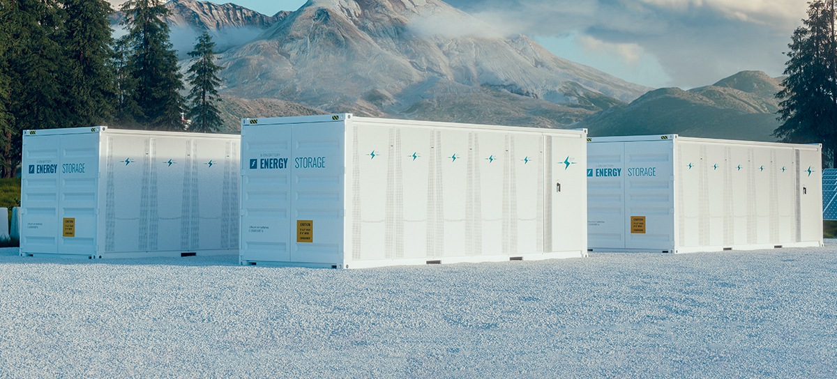
Our customer is a European company that creates software and hardware solutions for energy storage systems suitable for marine and stationary applications.
The customer needs to finalize the Battery Management System (BMS) firmware and develop software to interact with it.
We were also tasked with creating a module test station for testing the finished BMS before it could be sent to the buyer.
Solution
The BMS controls the operation of the li-ion batteries - LFP (LiFePO4) or NMC (LiNiMnCoO2).
Batteries are daisy-chained into a module. The module consists of 12 batteries. The module is supervised by the controller.
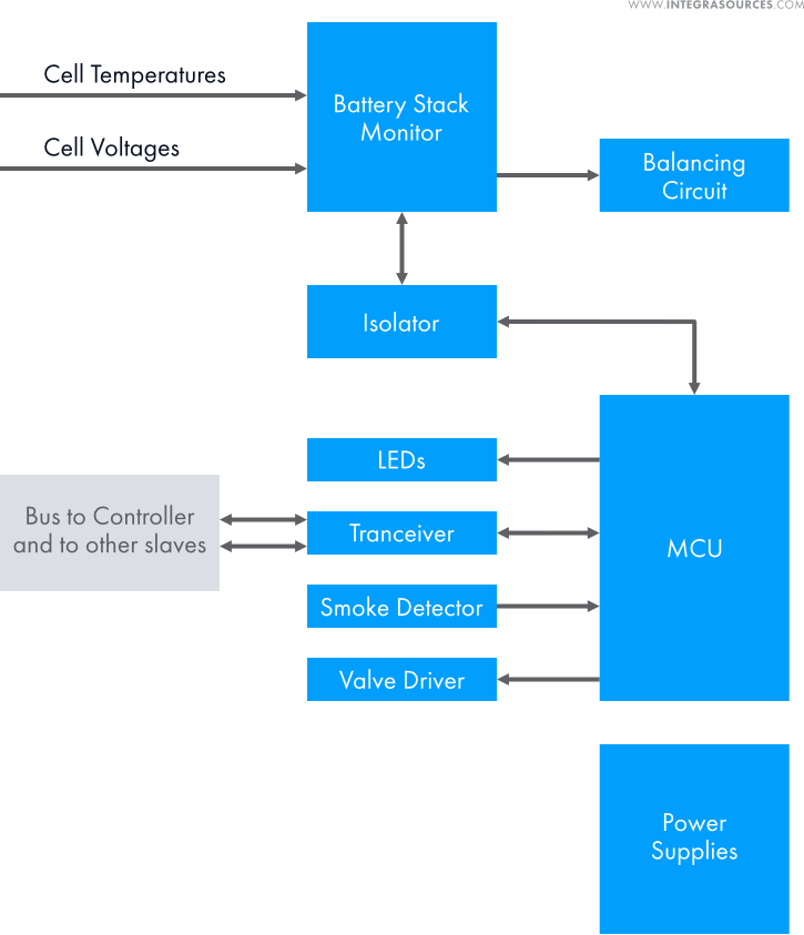
The module controller has to measure the cell voltage and temperature and report them to the control layer. Cell balancing is also performed here.
Balancing resistors are installed on each battery to equalize its charge level in the modules. Resistors perform passive balancing, smoothing the SoC difference of the batteries to a minimum value.
Twenty-four modules are united in series into strings. The total string voltage is slightly less than 1000 volts.
The string controller monitors the operation of 24 module controllers or one string.
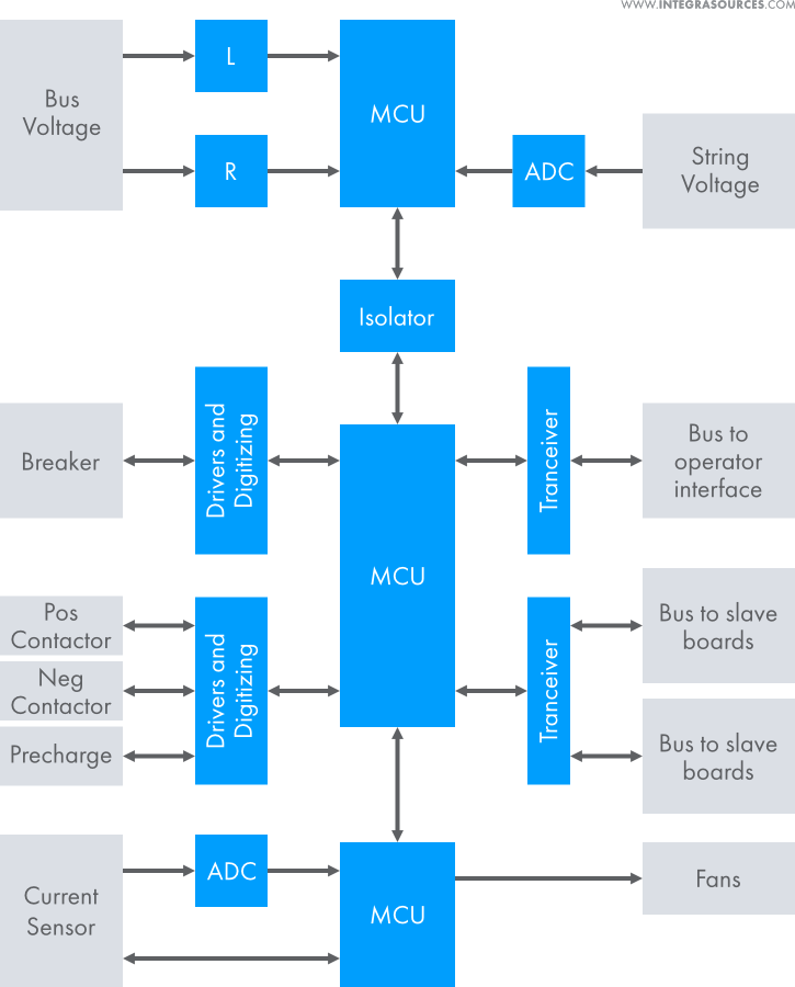
The string controller board is designed to perform the following functions:
- Bus control;
- Dual redundant bus to operator interface;
- Dual redundant power distribution control;
- Retrieving voltage and temperature measurements from the module controllers;
- Retrieving current measurements;
- SoC and SoH calculation;
- Cell balancing control;
- Circuit breaker control;
- Module contactors control;
- Alarm management;
- Emergency Stop management;
- Module fan speed control;
- Current limits calculation;
- LED control.
Up to 10 strings can be connected in parallel to increase the system capacity and power.
The power of one string is about 200 kW. Accordingly, the total system power can be up to 2 MW.
The BMS monitors voltage, temperature, and battery load current and measures string and bus voltages.
Based on the measured values, the BMS calculates the SoC (State of Charge), SoH (State of Health), and SoE (State of Energy) using a mathematical model created for these batteries.
BMS is a rather complex multi-component system, so our work was divided into several blocks.
Add-on Board Design
Our engineers have developed supplementary boards for BMS.
One of the PCBs is designed to control the valve on command from the module controller. It has a step-up converter to charge the supercapacitor since the board and the motor have different voltages. The engine gets connected to the supercapacitor when a command to control the valve is received.
The next PCB version we have developed has the same voltage as the motor and therefore does not need a supercapacitor.
Another add-on board we developed has an intelligent interface with an expansion port on the module controller. The board has three smoke detectors. When smoke is detected by all three sensors, a smoke signal is transmitted to the module controller. This approach eliminates false triggers.
Touchscreen Display App
We have created an application for a full-featured touch display. The application is used to check the current status of the BMS and its parameters, change the state of the BMS and its strings, and troubleshoot the BMS by checking alarm and data trends. It displays battery data and enables users to interact with the system.
It allows users to:
- keep track of battery parameters and states;
- enable/disable battery units; and
- acknowledge and clear up errors.
Any action that affects the system state is tracked in a special log. Such actions include the following:
- User login/logout
- Alarm acknowledging/clearing
- String Enabling/Disabling
- String Connecting/Disconnecting
- Other actions that change the BMS state
Battery Management System is a multi-level system, and each level has its own screen (page) that displays relevant information: the Home Screen, the String Screen, and the Module Screen.
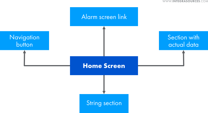
The Home screen shows the current BMS configuration, general data, and
string controller data: status, parameters, and connection configuration.
The String Screen contains the string ID, serial number, and actual parameters.
The screen displays all modules in the string and related information: the module ID, battery contactor status, module temperature, voltage, and SoC.
In the case of an alarm at the module level, the corresponding module is highlighted in color.
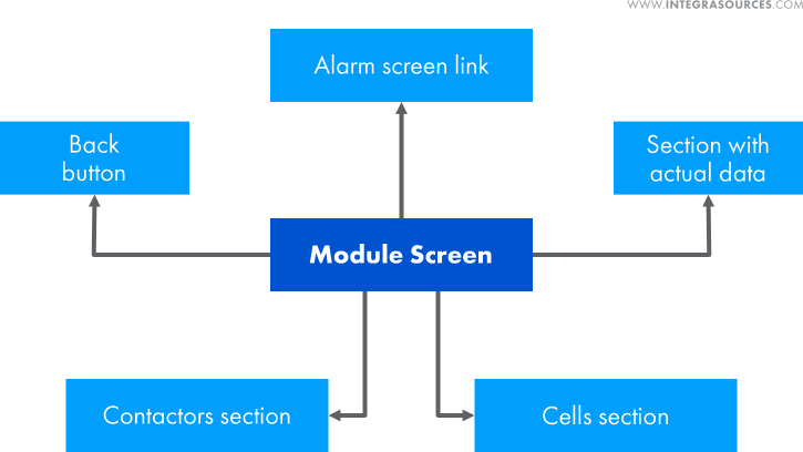
The Module Screen contains the module ID, serial number, and actual parameters.
Users can get information about each element's voltage, temperature, and SoC. The cells with the highest or lowest parameter values are marked with color.
In the event of an alarm at the cell level, the cell is highlighted with the corresponding alarm color.
On separate screens, users can view and manage alarms sent by the system.
The Alarm screen lists all active alerts and inactive unresolved errors and faults. With the appropriate access level, users can perform various actions: reset errors, acknowledge faults, and clear the alarm list.
The Alarm Logs screen lists all alarms ever raised in the system.
The system involves the delimitation of rights for users based on their involvement in the system control process. We have defined roles as User, Tech, and Admin.
An unauthorized viewer with a User role can check all BMS parameters, monitor trends, and check warnings/errors/failures.
Authenticated users with the Tech status can control the system on the System Control Screen; see Notifications and clear Error alarms.
Authenticated users with the Admin status have the highest access level. Having the Admin role means the user can change system parameters and acknowledge and clear Fault alarms.
Authenticated users (Tech and Admin user roles) have access to the Control Screen for managing the BMS (enable/disable, connect/disconnect strings).
We have implemented an OTP (One-time password) system, which allows users to receive a one-time password to log into the system and perform predefined actions.
Multi-String Manager development
We have implemented a server connected to all string controllers via Ethernet.
The multi-string manager monitors string status and receives telemetry and string alarms. The server itself can generate alarms. Depending on the nature of the alert, it responds by warning users, blocking the emergency string or the entire system, etc. Alarms are activated automatically without user intervention.
Telemetry includes a long list of parameters:
- cell voltage,
- temperature,
- the state of the sensors,
- battery voltage,
- SoH,
- time,
- amperage,
- bus voltage,
- discharge and charge limit,
- charging status,
- the maximum SoC limit,
- the maximum SoH limit,
- status of sensors and internal switches, etc.
The server stores all information in the database and sends it to the application.
When users interact with the application, the commands go first to the multi-string manager and then are forwarded to the string controllers.
The server can be accessed to obtain and manage data in a variety of ways.
- The touchscreen display controller displays system component status and alarms in a user-friendly graphical form.
- An external EMS (Energy Management System) can remotely control the BMS via Modbus TCP/IP protocol.
- With the help of the Redis database, users can connect remotely and view the system state.
- One can also manage the server using the gRPC protocol.
The multi-string manager server has a configuration file that defines limits and thresholds for system indicators, taking into account the total string power, battery capacity, and voltage.
BMS Security and Cryptography Feature Implementation
To meet the customer's requirements concerning BMS security, we applied encryption according to the Advanced Encryption Standard (AES) algorithm and signature using the Rivest–Shamir–Adleman (RSA) algorithm.
We have implemented such BMS security features as secure Bus to slave boards, secure initial firmware, and secure device firmware updates. We have created the necessary tools to automate firmware assembly and preparation.
High Voltage Interface
The high voltage interface measures bus voltage and current and distributes 220 VAC throughout the system where required. The interface also performs circuit breaker and contactor control functions.
Module Test Station development
We have implemented a module test station. The touchscreen desktop application tests the finished BMS module before the release.
The system should complete the required testing steps:
- to obtain a module controller’s serial number;
- to scan the QR code and write the value as the module serial number
- to verify the LED indicators’ operation
- to check the hardware integrity,
- to check if the elements’ voltage is within the specified limits,
- to get data from temperature sensors
- to get data from smoke sensors
- to check the valve operation (in case of fire, the valve opens, and the fire extinguishing system is activated)
- to verify the ability to charge cells,
- to display test results.
The results are generated in a separate JSON file. It is possible to change the parameters during testing, for example, depending on the battery type, etc.
Device Firmware Update Service Implementation
We have implemented device firmware update services for string controllers, module controllers, and the high voltage interface.
The customer can remotely update the firmware for devices.
Major Issues Resolved
BMS is a large and complex structure with many interconnected components. Before starting work on the project, we studied the system principles.
It was necessary to develop the firmware, considering the hardware system architecture and the customer requirements.
A BMS is a multi-component system with different communication interfaces between elements: Ethernet between the server and the string controller; RS-485 between the string controller and the module controller; I2C between the module controller and additional boards.
We needed to monitor all parameters and poll module controllers, additional boards, and sensors (current sensor, string voltage sensor, bus voltage sensor).
An additional challenge is to provide the ability for simultaneous firmware updates. A particular utility should be launched on the multi-string manager server for the device firmware remote update.
Another requirement was to ensure system security. In the case of an illegal connection to any system component, attackers should not get the data protocol structure and the data structure inside the system. Similar requirements concerned firmware security.
Our challenge was to ensure synchronous measurements of the cell, module, and string parameters. SoC calculation is also a complicated task related to battery characterization.
The Scope of Work
- Firmware development and testing
- PCB design
- Software development
- OTP (One Time Password) and cloud logging system development
- Management System development
- UI development
Technologies Used
- The software is written in C/C++.
- We used the Qt framework with its instruments: Qt Serial Port, Qt Virtual Keyboard, Qt Core 5, and Qt Network for app development.
- We used the MATLAB platform to build a mathematical model for battery state estimation.
- The application runs on Linux and can also run on Windows.
- The CLion IDE is used for software development.
- Altium Designer is used for schematics and PCB design.
- We used SEGGER J-Link tools for debugging.
- The multi-string manager server can be accessed for management using Modbus TCP/IP and gRPC protocols.
- The Redis database is used for external connections and system status views.
- The customer has chosen the NXP MKL17Z256VFM4 and the NXP MK66FN2M0VMD18 microcontrollers for BMS.
- The firmware is written in C/C++.
- Analog Devices LTC®6811 multi-element battery stack monitors are used to measure the battery voltage.
- We used NXP’s MCUXpresso software and tools for firmware code development.
- The C++ template library Eigen for linear algebra is applied for SoC estimation.
- Data is stored locally on PostgreSQL.
- We have applied AES and RSA algorithms to ensure the system’s security features.
- The tools for automating firmware assembly and preparation are written in Python.
- FreeRTOS is used for firmware development.
Result
Our BMS is a vast system comparable in capacity to a small hydroelectric power plant.
Our engineers designed additional boards for fire safety and a server for BMS management. We wrote firmware for all system components and created a touchscreen display application for user communication with the BMS. We have also implemented automated testing software.
The result matches the customer’s requirements.
The project is constantly evolving. Small features are being added, and bugs are being corrected. Two releases of the system have already been made. We are currently working on the next updated version.
Maximum System Power
Battery type
Maximum number of cells
Support for
You might also like...
Industrial Gas Burner Controller
A supplier of industrial automation solutions asked Integra Sources to design a controller for industrial gas burners capable of competing with products from leading market players.
LEARN MORE

Otoacoustic Emission System
With its advanced probe, the system captures two types of otoacoustic emissions: TEOAE and DPOAE. Results are saved directly to the device’s memory and can be printed via a connected thermal printer.
LEARN MORE


