

Aircraft Towing Protection System
Backstory
Concern for the aircraft's safety does not end with landing. Collisions of airplanes with obstacles and other aircraft during taxiing and towing result in high insurance claims every year.
Therefore, it is crucial to ensure aircraft safety during towing to prevent accidents on the ground and, hence, save money.

Request
The company that provides aircraft maintenance services asked us to develop an aircraft towing protection system.
The system consists of devices with sensors placed on small aircraft, a mobile application, and a web portal.
Parking sensors determine the distance to objects and transmit data to the application. In addition, they have cameras and send the video stream to the app. Thus, the operator can see obstacles on the tablet screen.
The web portal receives data from the application, collects statistics, and manages an aircraft towing protection system.
Solution
The device is used for safe aircraft parking on the ground and in hangars. The object is equipped with an accelerometer, GPS, distance-measuring tools, LEDs for light signaling, and a buzzer for beeping.
The module we created has two PCBs. One of them is an indication board that makes the module perform as a parking light. The board has three powerful RGB LEDs and an LED controller.

The main board houses an IWR6843AOP antenna-on-pack device from Texas Instruments. The 60-GHz mmWave sensor platform measures the distance to obstacles.
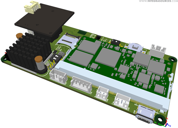
After trying options with the Orange Pi and Raspberry Pi as the main processing units, we opted for a VAR-SOM-MX8M-NANO system-on-module (SoM). The SoM is a separate board with a processor, peripherals, Bluetooth, and Wi-Fi modules for communication.
The device is battery-powered. According to customer requirements, we used a 7.4V battery for the Harris P7100 radio due to the rugged battery case. The battery contains two series-connected lithium cells, which required a specific charger (we used MAX77962EWJ12+T) and slight changes in the PCB design.
Four IR LEDs around the camera illuminate objects. The camera picks up infrared radiation reflected from the object and thus can see in the dark. LED brightness is adjusted depending on the photosensor readings.
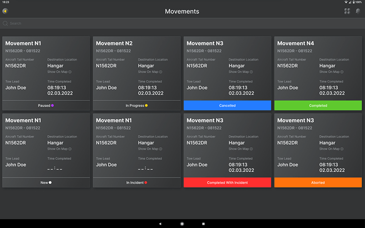
Using the Android application, the employee responsible for the towing can create towing tasks, enter towing session parameter data, generate incident reports, and enter information about the sensors placed on the aircraft.
The aircraft tug operator enters his name, aircraft tail number, destination, and other information to start a towing session.
Weather conditions, such as temperature, humidity, wind, etc., are auto-filled from weather services for insurance purposes and to understand weather conditions that could contribute to an incident.
The app then starts scanning the BLE network in the area. After detecting the modules and checking their ID with the available list of modules registered to the operator, the application connects to the devices.
It sends them the Wi-Fi and TCP server details for the modules to connect to the app via Wi-Fi.
Once the connection is established, the mobile app and the devices exchange initial data. The app transmits trigger threshold settings to the modules.
The thresholds are the distances to an obstacle that the modules consider safe, close, or dangerously close.
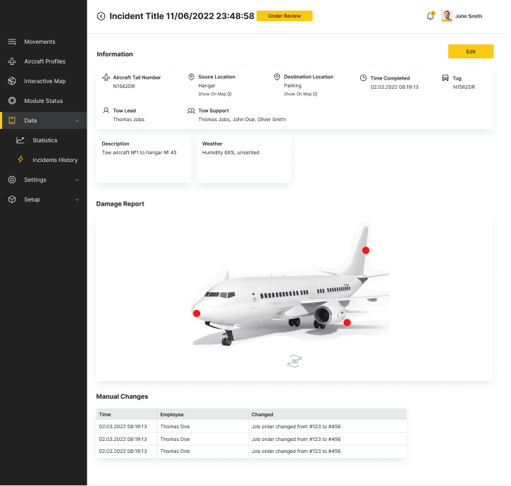
When the operator installs the scanning modules on the aircraft, he can mark their locations on the plane's 3D image in the app. The information from each scanning module is sent to the tablet application.
The operator can see the modules' location on the plane and the distance from each device to the closest obstacle marked with green (safe), yellow (warning), and red (dangerous) colors.
The modules also stream video data from the camera to the app via the RTSP protocol, allowing the operator to assess the situation in real time.
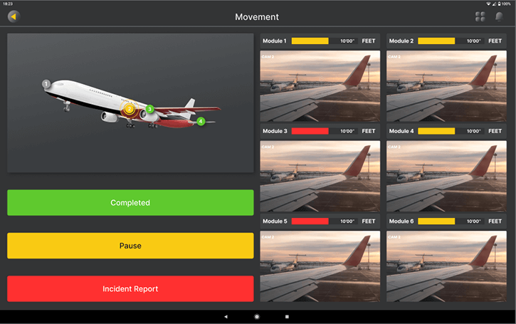
If there is an obstacle on the way, the module starts beeping. As the obstruction gets closer, the beeping speeds up, thus warning the operator about the danger.
The mobile application allows the operator to create damage reports (if an incident occurs during the towing session) and pre-tow damage reports (if the damage is discovered before the session begins).
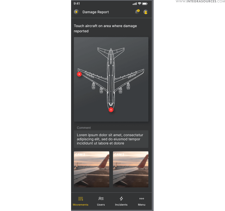
The operator can take pictures of the damaged areas, describe the damage, and fill out other relevant information. The data is sent to the web portal via RestAPI.
The mobile application is written in C++ and QML with the help of the Qt framework. It runs on Android.
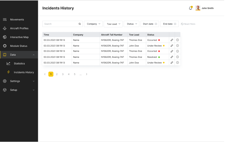
The administrative office can see the location of aircraft and towing vehicles, track current towing sessions, and manage system settings through a web portal. Operators can fill out aircraft and equipment handbooks, obtain session-related statistics, and receive damage reports and video data.

The web portal also has 3D aircraft models with recommended sensor placement points.
The map that shows aircraft locations is based on Google Maps. It displays the current aircraft positions based on GPS coordinates transmitted from sensors.

We implemented authorized access to the web portal and the function of adding a user. These features are required because the customer plans to sell the system to airfield owners. User roles are divided into three groups: super administrator (developer), administrator (airport manager), and user (airport controller).
Major Issues Resolved
We used the Orange Pi as the main processor unit at an early stage. Since the Orange Pi didn't work properly with Bluetooth and the CSI camera, we decided to use the Raspberry Pi instead. In the final version, we replaced the Raspberry Pi with a system on a module (SoM).
Initially, the client part of the application was developed in Python. We rejected this idea due to performance issues. Using the Qt framework, our specialists created an embedded application with fast and effective BLE and TCP support.
Qt allowed us to use the Wiring Pi library to communicate with an external buzzer and an I2C LED module.
We ran into a radar cooling issue. Due to the presence of the antenna, it was impossible to install a heatsink on top of the microcircuit; this would interfere with radar operation. We got out of the situation by installing a heatsink on the back of the board using a thermal pad. Heat is taken away through the PCB holes.
The parking sensor's buzzer was not loud enough for such a noisy place as an airfield. Therefore, we used a boost converter in the circuit. The converter raises the battery voltage to 38 V, causing the buzzer to signal an obstacle very loudly.
The Scope of Work
- Schematics and PCB design
- PCB assembly, testing, and fixing
- Firmware development
- Mobile app development
- Web development
Technologies Used
- We used Altium Designer for schematics and PCB design.
- We wrote firmware for the scanner unit in C++ using Visual Studio Code.
- After trying out the Orange Pi i96 and the Raspberry Pi as the main processing units, we finally chose a VAR-SOM-MX8M-NANO system-on-module.
- A 7.4V battery for the Harris P7100 radio powers the module.
- We used the Analog Devices Inc. MAX77962 3.2A USB Type-C® Buck-Boost Charger for battery charging.
- A low-light USB camera USBFHD06H-L170 (Fisheye) is used for making videos.
- We wrote the application for Android using the cross-platform Qt framework, C++, and QML.
- The IWR6843 antenna-on-pack device from Texas Instruments measures the distance to the obstacle.
- The CPE-827 buzzer from CUI Devices makes signals when moving toward an obstacle.
Result
Integra Sources’ team developed a hardware and software system to help airport personnel during aircraft towing. We created a full-fledged sample device for submitting geolocation data, measuring the distance to objects, and giving sound and light signals during aircraft towing.
Device data is transmitted to the tablet application. The app helps operators to carry out aircraft towing safely, avoiding collisions. The app has a 3D aircraft model with sensors marked on it.
The web portal is intended for system management and prompt response by the airport administration to emergencies, primarily collisions.
The web portal contains information about the aircraft and vehicle fleet, 3D models of aircraft with sensor installation points, a list of hangars, an employee database, and towing statistics.
Administrators can track the towing of any aircraft in real time. The portal receives geolocation data from the mobile application. In the event of a collision, the damage report and video data are sent to the portal.
The system we have developed will help airfield owners and servicing companies improve towing safety, minimize towing incidents, and save money.
You might also like...

Monitoring System for Office Plant Care
The system tracks soil moisture and other parameters and alerts users when watering is needed. The project included gateway design, as well as mobile and web applications development with Flutter. 
LEARN MORE 

Coffee Roaster Management System
Our team of engineers and software developers has designed a flexible coffee roasting machine control system featuring automated modes, an intuitive user interface, and a suite of convenient functionalities. This solution enables roaster operators to rapidly adapt to evolving conditions and scale production processes while ensuring consistently exceptional coffee quality.
LEARN MORE