This website uses cookies so that we can provide you with the best user experience possible. Cookie information is stored in your browser and performs functions such as recognising you when you return to our website and helping our team to understand which sections of the website you find most interesting and useful.
System and Application Software for Monochrome and RGB LED Matrix Display
Background
The Intelligent Transportation System (ITS) provides traffic management services and keeps users informed, enabling more efficient and safer driving, provoking speed reduction, and helping to resolve traffic jams.
Urban Traffic Management Control (UTMC) is a UK program for effective ITS implementation in urban areas.
UTMC systems allow the various applications to interact and exchange information. Data collected from multiple sources such as automatic license plate recognition (ANPR) cameras, variable message signs (VMS), parking lots, traffic signals, and air quality monitoring stations are available in a single database. With timely data, authorities can effectively address traffic congestion problems, ensuring safer driving and reducing emissions.

Request
A UK company designing and manufacturing vehicle speed detection and LED sign solution products reached out to Integra Sources. The company asked us to develop a software and hardware complex for controlling LED panels used as information boards on public roads.
Solution
The device is an LED display with a Single Board Computer that serves as an LED sign with variable messages for road users. It can be connected to the Intelligent Transportation System using a web portal, MQTT and UTMC protocols.
UTMC is a free protocol that is currently the British standard for ITS. Most UK local governments have a UTMC core in their systems.

The customer has chosen the Single Board Computer along with the LED panels. We were responsible for developing a software and hardware complex.
The system consists of four parts:
- It has LED panels controlled by TLC5924, TLC5958, and TLC59581 chips. The panels have 512 monochrome or RGB LEDs arranged in a 16x32 grid and can be daisy-chained into a large display of up to 256x256 LEDs, i.e., 128 panels. The output of one panel is connected to the input of the next one along the line.
- The system has an LED panel controller based on the SoC Zynq 7020. The tasks of the controller include the following:
- FPGA control of the TLC5924, TLC5958, and TLC59581 LED drivers
- Support of a service providing an external user interface via MQTT and UTMC protocols and a web portal (user interface).
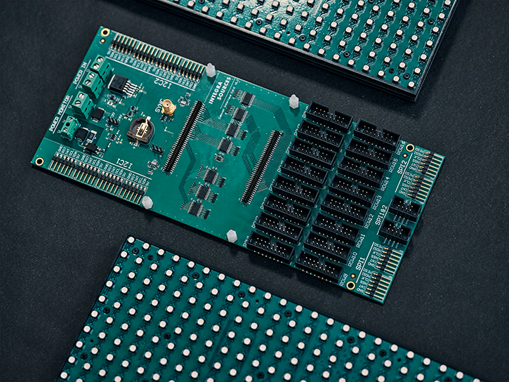
We designed an expansion PCB to ensure the proper operation of the microcomputer with LED panels.
The card has certain functionality:
- Coordination of input and output signal voltage levels between the control system (FPGA) and panels
- Protection against electrostatic discharges (ESD)
- Making it possible to connect an external differential synchronization signal
- Power source support:
- The device can be powered from two independent external 5 V sources (one is primary, and the other is backup) with automatic switching between them.
- Power management system support:
- The system compares switchable 12/24V voltage levels against hardware-defined thresholds to control external sources or UPS (Uninterruptible Power Source) batteries.
- The system determines the absence or presence of AC voltage (120/240 V).
- If the problem with the above sources occurs, it can send a power failure signal to the FPGA.
The CR1220 battery is a backup power source for the power management system in case of a blackout.

A microcomputer running Linux is connected to the LED panel. We have developed a system service that monitors and controls the device. The user can access the application through the web page to manage the device’s operation.
Firmware
We had to write the FPGA firmware and get the bitstream. The bitstream should receive data from the processor and output it to the LED panel.
The FPGA firmware is implemented in Verilog.
When developing the firmware, we made two main iterations. One of the workstreams was related to the monochrome matrix, and the other referred to the RGB matrix.
During the firmware development, we added a ready-made Xilinx CDMA (Central Direct Memory Access) IP core to the basic version for reading and transferring memory data without the processor’s involvement. We also wrote a module for reading the DNA register.
Our developers used the Vitis software platform for testing before handing off the bitstream to the development team. Vitis provides an SDK (a Software Development Toolkit) and BSPs (Board Support Packages) for convenient work with Direct Memory Access.
Using Vitis, we created FSBL (the First Stage Bootloader) for the Zynq 7020. The bootloader loads the bitstream, then loads the firmware and launches it.
We conducted firmware tests with writing test benches on Verilog. Our designers also wrote and ran bare-metal C programs to test the system's functionality.

Software
The application has three interfaces, which together provide the necessary operations:
- Sending text messages and images to be displayed on the panel
- Scheduling messages and icons to be displayed
- Calibrating the signal sent to the LED panel to level out the gradual dimmer effect of some LEDs
- Getting LED failure data
- Receiving device telemetry data (humidity, light, and temperature)
Device status data is required, among other things, for the automatic switching of heating and cooling devices. Users can also change the conditions for system activation.
The software was written in C++, with the UI based on JavaScript and HTML.
The application supports MQTT, UTMC, and web portal access channels, each of which has its own login and password authentication method.
Major Issues Resolved
We were tasked with integrating LED panels, FPGA, a web interface, and software into a single system so that all components could function properly.
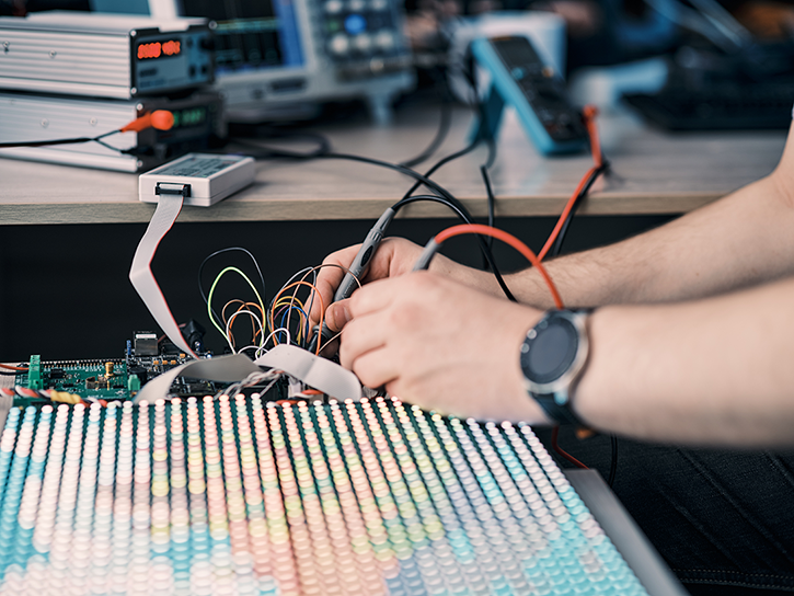
At the stage of creating the firmware, the main difficulty lies in finding and eliminating errors during testing. We can get the internal circuit generated in the wrong way with some incorrect signals, affecting the overall functionality. Such things are hard to find and debug.
We used dedicated tools like a Xilinx Integrated Logic Analyzer (ILA) IP core to monitor the FPGA's internal signals.
We also encountered the need to debug the AXI bus due to error writing to registers. We used a particular analyzer provided by Xilinx to check the signal processing correctness. The analyzer allows us to validate the AXI bus, verify its state, and detect errors.
The Scope of Work
- Firmware development and testing
- PCB design
- Software development
Technologies Used
- The software is written in C++, providing the necessary performance and greatly simplifying development. We used the BOOST C++ libraries.
- We used JavaScript and HTML to create a web portal (user interface).
- We used a Linux-based Debian operating system as a basis for software development.
- Altium Designer is used for schematics and PCB design.
- We used MQTT and UTMC libraries for organizing messaging using the MQTT and UTMC communication protocols.
- The SQLLite database is responsible for persistent application data storage.
- We used the ILA IP core, the CDMA IP core, the Vitis software platform, and other Xilinx tools for firmware development.
- The FPGA firmware is written in Verilog.
Result
We have developed firmware and software for a device that will be used as an LED traffic variable message sign (VMS). By joining forces, our specialists from the software and hardware teams have achieved well-coordinated work of the LED matrix, FPGA, web interface, and software in a single system. However, software development is still in progress. An RGB driver to support color panels is awaiting further construction.
The Monochrome LED Matrix Refresh Rate
LED Panel Pixel Height and Width
Maximum Possible LED Display Pixel Height and Width
Support for
You might also like...

Industrial Gas Burner Controller
A supplier of industrial automation solutions asked Integra Sources to design a controller for industrial gas burners capable of competing with products from leading market players.
LEARN MORE

Otoacoustic Emission System
With its advanced probe, the system captures two types of otoacoustic emissions: TEOAE and DPOAE. Results are saved directly to the device’s memory and can be printed via a connected thermal printer.
LEARN MORE


