

Designing a BMS (Battery Management System) for a Stationary Battery Storage Solution


Battery management systems (BMSs) can supervise batteries operating in a diversity of devices and applications. The design of a BMS gets sophisticated according to the complexity of the solution it is used in. Thus, in addition to the minimum structure and functionality, the system can acquire extra elements, modules, and levels. This post covers different types of BMS arrangements and configurations and goes into detail about the custom hardware design of a BMS intended for a stationary home energy storage solution. Here, you’ll learn what components to use and how to connect them to build a solid BMS architecture. Also, you’ll come to know the main challenges arising in the BMS design process.
The ABCs of BMS Design
Battery management systems monitor and optimize battery charge and discharge cycles to help ensure battery performance, longevity, and protection from damage.
The BMS market is growing at a rapid pace, driven by the trend toward clean energy and the boom in the consumption of devices and systems using rechargeable batteries.
Thus, according to Spherical Insights, the global BMS market will grow more than sixfold in the next decade, from $7.9 billion in 2022 to an expected $48.4 billion by 2032.
Either simple or complex, any battery management system has a set of essential functions and specific components to implement them. Then, the more requirements you have, the more elements you need to add to your system. Now, let’s look at the core BMS functionality.
Principal BMS Functions
A BMS comprises several significant tasks necessary to manage a battery. It’s worth mentioning that each function can be supported by a number of functional blocks and electronic components.
Battery monitoring
Using various sensors and measurement units, a BMS monitors the parameters of the cells that make up a battery. Depending on your system’s demands, a BMS can measure the battery’s current, voltage, and temperature.
Battery control
The primary goal of a BMS is to keep a battery within its safe operating area. It can balance cells, calculate the state-of-charge (SOC) and state-of-health (SOH), and protect the battery from overrvoltage, overtemperature, and other out-of-limit conditions. A BMS controls charging and discharging and can disrupt these processes to save the battery from possible hazards.
Communication
This function lies in transmitting signals between the internal parts of a BMS as well as external devices and systems connected to it. For example, a BMS can display the battery data on a dashboard or human-machine interface (HMI). A charger can be a part of a BMS or a separate device, and it’s crucial to establish a connection between them. BMS communications can be wired or wireless.

BMS Topology
The components of a battery management system can be arranged in several different ways. These arrangements, called topologies, can be centralized, distributed, and modular.
Centralized BMS topology
In a centralized topology, there is a single BMS printed circuit board (PCB) with a control unit that manages all cells in a battery through multiple communication channels. This type of arrangement makes a BMS a bulky, inflexible yet cost-effective solution.
BMSs with centralized topologies dominate the BMS market because the design and construction of such systems are simpler and cheaper than other topologies. Grand View Research notes in its report that in 2022, centralized BMS accounted for more than 43.0% of global revenue.
Distributed BMS topology
Here, every battery cell has its own BMS PCB, and a control unit is connected to the entire battery through a single channel. The daisy chain is one of the distributed topology variations intended for systems that have a small need for fault tolerance. Distributed BMSs are easy to deploy but costly because of the abundance of electronics.
Modular BMS topology
A modular BMS is a combination of the above two topologies. This arrangement is also known as decentralized, star, or the master and slaves topology. There are several interconnected control units (slaves), and each of them oversees a group of cells in a battery. The slaves are connected to the main control unit or master, which handles the integrity and safety of the whole battery. A modular BMS topology can provide a balance between the price and design complexity.
Precedence Research's analysis shows that the modular topology segment of the global BMS market will grow at the fastest pace in the next decade.

Apart from various BMS topologies, there can be three different ways of organizing cells in a battery pack—you can connect them in series, in parallel, or make the connection series-parallel. The serial combination can raise the voltage of the battery; the parallel connection can increase its capacity; the series-parallel configuration can boost them both.
BMS Configurations
BMS types and configurations vary in the number of modules, levels, and subsystems. BMS functionality can be implemented with the help of simple circuitry or a set of PCBs with microcontrollers (MCUs) and firmware. On top of that, larger and more sophisticated battery management systems may use complex BMS software and algorithms.
A BMS can be a no-brainer solution attached to a battery of a simple electronic device. Here, it can only monitor the basic parameters and run the charging process. Normally, such battery management systems have a minimum set of components, including a control unit, a measurement device, a charger, and a battery itself.
Being part of a battery energy storage system (BESS), a BMS can have many more things to do and may need a bigger size, higher power, and broader functionality. A BMS installed in a microgrid, black-start solution, uninterruptible power supply (UPS), or another BESS, will have a multimodular and multilevel structure.
Reliability and fault tolerance are the most important factors affecting the complexity of BMS design. If a battery-operated system performs a life-critical function, for example, serves as an emergency power system for a hospital, it definitely requires strong battery control. A battery storage device working in extreme environments will need increased protection and a range of BMS safety features.

Within our power electronics design services, we created battery management solutions of varying difficulty, ranging from a simple BMS to a state-of-the-art device integrated into a larger energy storage system.
In this article, we’ll consider a solution of medium complexity: our custom-made BMS geared towards a lithium-ion battery stationary home energy storage device. This will be a vivid example of BMS design fundamentals.
It should be noted that the popularity of lithium-ion batteries around the world is growing due to their wide application in a wide range of devices, from electric vehicles to battery energy storage systems. Spherical Insights says that the lithium-ion battery segment is expected to have the highest CAGR in the global BMS market from 2022 to 2032.
Here, we focus on hardware design and electronics. For BMS software development, you can check a related post on our blog.
The Full Story of Our Custom BMS Design
In this project, we took care of the complete cycle of electronic design, including PCB design and layout, and firmware development. As a result, we’ve got a full-fledged battery storage solution for low-voltage residential applications.
Our BMS is a flexible and scalable product that allows for various configurations. The system’s maximum output characteristics are:

BMS Architecture
As a part of a BESS, our BMS had to fulfill a good deal of functions, which defined the choice of building blocks and architecture of the system. To cover all the bases, we selected the following components and technologies:

For our system, we opted for a modular or decentralized topology with a few arrays of batteries supervised by control units or power cells (PCs). Each PC is responsible for 8 batteries, that is, it balances the cells and measures their voltage and temperature using the respective sensors.
In our customized BMS design, we used the series-parallel configuration of battery cells. First off, it allows the user to connect batteries in series from 1 to 8 cells, increasing the voltage from 24 V up to 200 V. In their turn, the power cells can be joined in parallel from 1 up to 4 arrays.
The PCs of one array are connected to a multiplexer (MUX) that reads error signals from the control units and generates a single output signal. Also, the MUX device measures the current of the batteries in its array via a current sensor. We installed fuses in the circuit to protect the batteries from overcurrent.
Each battery array has a cutoff switch that can disconnect the array from the entire battery to save energy during charging. In addition, the cutoff switch can break the circuit in case of emergency, for example, if the battery is charged with the wrong voltage.
Every PC has a positive and negative output (terminals of the battery), an RS-485 interface to communicate with other control units and the multiplexer, and an IRQ to report errors.
The MUX devices send RS-485 and IRQ signals to a single-board computer (SBC), which is the brain of the BMS. The SBC interrogates the control units one by one, makes all the calculations, determines the SOC and SOH, controls charging, discharging, and other processes and states of the battery. The SBC has a real-time clock, memory, an RS-485 line to connect with the BESS, and an LED display that shows the current status of the system. Ethernet and BLE interfaces enable the user to communicate with the BMS remotely.
Within our firmware development services for this project, we also built a custom embedded Linux image for the SBC, implemented an RTOS in each power cell and MUX, encrypted Ethernet and BLE communications to secure the system and its users from unauthorized access and data misuse.
This diagram shows how we arranged the above components and what BMS architecture we shaped:

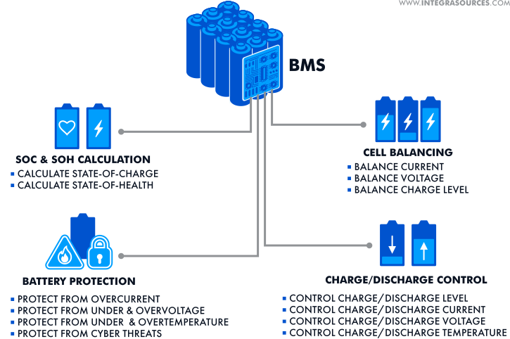
BMS Functionality
Each of the components stands behind an important activity or activities aimed at monitoring, controlling, and safeguarding the battery. The following is the list of functions that our bespoke battery management system performs:
Battery protection: Our BMS offers all must-have tools to defend the battery against potential threats. For starters, the system measures the battery parameters and compares them with the setpoints. Then, the BMS can disconnect the circuit and save the battery from overcurrent, under and overvoltage, under and overtemperature. In addition, the system protects the confidentiality and integrity of the data transmitted.
Charge/discharge control: Improper charging can seriously damage or completely disable the battery. The BMS help observe the battery’s charging/discharging level and conditions. These conditions comprise voltage, current, and temperature limits. The BMS alerts the user in case the battery reaches its critical level or the parameters go out of range.
SOC and SOH calculation: Estimating the battery’s state-of-charge and state-of-health is vital for the efficient and long-lasting operation of the battery. Our BMS can accurately calculate the SOC and SOH thus giving a clear picture of the current battery status, including the depth of discharge (DoD), capacity, wear level, and other characteristics. The SOC and SOH estimations assist the user in maintaining the battery and predicting its future behavior.
Cell balancing: The battery installed in our custom BESS contains plenty of cells, which cannot discharge equally and have the same level of voltage or current. The BMS adjusts the charging level and parameters of the cells, making them even. This minimizes the wear level of the battery and enhances its performance.
BMS Challenges
For an expert, the design of a battery management system is a common engineering task, lacking apparent problems. That’s why the skill level of a development team is instrumental in BMS design.
Making a robust solution demands high qualifications in a variety of technologies and engineering fields, such as batteries, power electronics, embedded hardware, and embedded software development. To get the desired result, you need to make sure your project is handled by true experts.
We at Integra Sources have extensive experience with different rechargeable batteries and wide voltage and power ranges. Our engineers have created simple and complex BMS designs for a host of applications—from small consumer devices to large-scale energy storage solutions.
In this particular project, we didn’t face daunting challenges, but there were some things that we had to busy ourselves with. The main issues concerned firmware for the SBC and communication interfaces. For example, we struggled a little to achieve a satisfactory data processing speed without exceeding the initial project budget.
Balancing battery cells can be quite a challenge for a BMS designer, but most difficulties here relate to software rather than the hardware development process. We’ll elaborate on cell balancing and its implementation in one of our next posts.
It’s critical to design a BMS with the relevant regulations in mind. Your product will never come out unless it meets all the necessary standards.
Depending on the industry and area of application, battery management systems may have different certification requirements. A BMS designer must consider them at every development stage—from component selection to QA testing and preparation for manufacturing.
As for our system, it was certified together with the BESS under a range of standards and certifications concerning safety and environmental protection. Among them are:

Conclusion
The core functions of a battery management system encompass monitoring the parameters of a battery, controlling its condition, and communicating the results to the user and related devices. Extending the functionality means adding more components, functional blocks, and levels to the system.
BMSs can have diverse topologies (centralized, distributed, and modular) and configurations that depend on the system’s requirements and application. Thus, a battery management system that needs higher reliability and fault tolerance will have a more complex structure and elaborate design.
In this post, we gave an insight into the hardware design of a BMS that manages the battery of a low-voltage stationary system used for residential energy storage. If you’re interested in creating a BMS for a more powerful application or, conversely, a simpler device, you can learn everything there is to know by speaking with us directly.
Related
materials

Battery Management System Development
Integra Sources reviewed the hardware and software of the battery management system. We provided PCB, firmware, app, and server development.
LEARN MORE 
LEARN MORE

Battery Management System (BMS): Effective Ways to Measure State-of-Charge and State-of-Health
We’ve picked out tried-and-true methods of estimating the battery’s state-of-charge and state-of-health to share them with you.
LEARN MORE
LEARN MORE

Shortly about BMS design in Infographics
We have prepared another infographic on BMS Design. Check out the basic summary in the infographic and read the full...
LEARN MORE
LEARN MORE