This website uses cookies so that we can provide you with the best user experience possible. Cookie information is stored in your browser and performs functions such as recognising you when you return to our website and helping our team to understand which sections of the website you find most interesting and useful.
DC Motor Controller Design
Backstory
Robots help people in a variety of ways — they optimize manufacturing processes, assist with surgical operations, explore space, and perform many other functions. Nowadays, robotics has become an accessible technology that doesn’t require special engineering skills. With a rich choice of tools and kits available, building a robot is achievable, even for a kid!
Our partner creates robots, robot parts, and kits for both professionals and hobbyists. To match the rising competition, they wanted to extend their product line and offer new opportunities for their customers.

Request
The client came up with an idea to design multi-mode motor controllers to be used to remotely control DC motors installed in the robots. They planned to add more features to improve the performance of the devices and enhance the user experience.
The task was to develop a 2-channel motor controller with digital and analog inputs that could use open-loop and closed-loop control systems.
One of the basic requirements included wide operating voltage and current ranges. The client planned to create several versions of the device that could handle the operation of both low-power and high-power motors.
It was important to meet the project requirements and minimize development costs without compromising the device’s level of performance, functionality, and size.
Solution
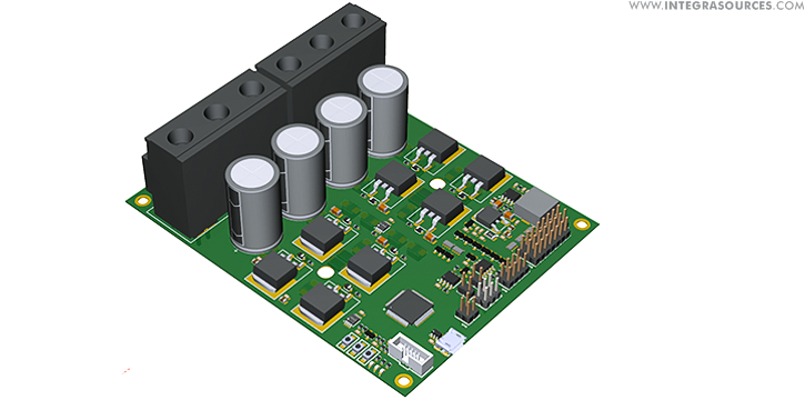
For the power side, we chose an H-bridge to design the schematic and PCB. This is a traditional motor controller circuit with two high-side and two low-side switches. An H-bridge circuit supplies voltage and reverses its polarity, thus enabling a motor to rotate in either direction.
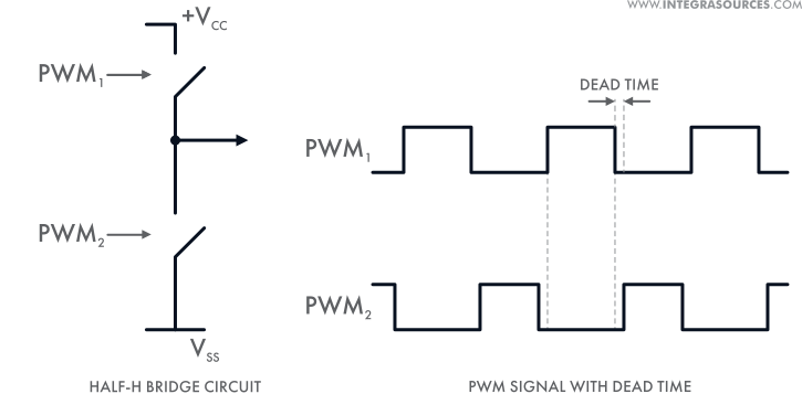
To regulate the speed and torque of a motor, we used a switching voltage regulator with pulse-width modulation (PWM). It supplies voltage in pulses by adjusting various duty cycles (the ratio of the pulse to the pulse period).
Our circuit design enables the motor controllers to manage the operation of both brushed (BDC) and brushless DC (BLDC) motors and switch between the modes.
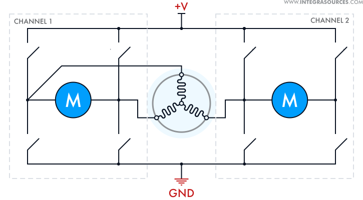
The controllers allow the connection of a Hall-effect sensor in the BLDC mode. The devices have 2 channels to handle a BDC motor and a single channel for the brushless mode. Every channel can have up to 2 terminal switches to manage extreme positions of the mechanics.
Analog sensors mounted on each arm of the terminal stages allow the controllers to calculate back electromotive force (back EMF). Measuring back EMF helps detect the rotor’s position in a BLDC motor and thus controls its operation. In addition, it supports the braking modes of a BDC motor.
The controllers have analog and digital inputs and support a variety of communication interfaces, including UART, RC, CAN, and RS-485.
We created several versions of the device with varying operating voltage and current ranges. Our low-voltage controllers have power MOSFETs. In the high voltage version of the controller, we replaced MOSFETs with IGBTs for higher output power.
To receive feedback from a motor and adjust its speed, a user can connect a digital quadrature encoder to the motor controller. The controller’s firmware will leverage data from the encoder to regulate the motor’s speed. In addition, we implemented a proportional-integral-derivative (PID) algorithm. It analyzes a motor’s speed, compares it with the setpoint, and calculates PWM signals to regulate the speed of a motor and the distance traveled.
To prevent shoot-through in the H-bridge circuit, we implemented dead time that enables transistors to switch on and off in turn with minor delays.
To set the parameters of the controllers, we created a cross-platform desktop application.
Main Challenges Solved
The most challenging task of the project was to provide a wide operating range of current and voltage and avoid overheating. To achieve this, we had to consider different design options and pay special attention to the selection of components and PCB layout. As a result, we created several motor controllers that can operate steadily at 10 A and 20 V, 30 A and 40 V, 60 A and 60 V, 150 A and 60 V.
Another challenge was related to the size of the device. Apart from the high output power, we had to add a set of features that could fit in with a small-sized board.
Scope of Work
The motor controller project involved electronic design and firmware development. We created custom schematics, selected suitable components, and designed PCB layouts.
At the low-level programming stage, our engineers wrote custom firmware and algorithms to ensure the efficient performance of the motor controllers.
We tested the prototypes and prepared a bill of materials (BOM) and Gerber files for mass production.
Technologies Used
- We used Altium Designer IDE for schematics and PCB design.
- We wrote custom firmware in C/C++ using STM Studio.
- The controllers are based on older versions of STM32F4 microcontrollers and the new STM32G0 series.
- For the circuit design, we selected power MOSFETs and IBGTs.
- The device supports analog, digital, serial (UART), CAN, RC, RS-485, and USB communications.
- We used FreeRTOS for firmware development to provide the controllers with real-time responses to external events.
- The device can operate in a 2-channel BDC mode and a single-channel BLDC mode.
- We built a cross-platform desktop application using C++ and the Qt framework.
Result
We created a complex hardware and software solution for building motor controls with a wide range of features and operation modes. The devices can switch between the modes and control brushed and brushless DC motors, using either an open-loop or closed-loop system. We designed several versions of single-channel and 2-channel motor controllers with analog, digital, serial (UART), CAN, RC, and RS-485 inputs.
The motor controllers can start and stop a motor, reverse its rotation, manage its speed and torque, and determine its position. The devices can use simple control commands or a mode with programmed behavior that allows for programming a particular sequence of actions.
The controllers can use differential steering, so each input channel can handle either one track or two tracks of the robot, spinning them at different speeds independently of each other. A special mode enables the controllers to start and stop the motor smoothly and avoid wheel slip. This can help users estimate the distance traveled by the robot and determine its position.
The motor controllers have overcurrent, overvoltage, and overheating protection systems that ensure their safe operation.
Focusing on component selection and PCB layout, we created a cost-effective design solution that provides stable and efficient operation of the motor controllers within wide voltage and current ranges.
Current and voltage ranges for different motor controller versions:
You might also like...
Vibration Conditioning Solution for Industrial Automation
The solution measures industrial machinery vibration. We implemented analog and digital filters that make the output signal smooth and strong.
LEARN MORE
Autonomous Robotic Lawn Mower
The robot has an autonomous navigation system with sensors and intelligent algorithms. We provided both hardware design to software development.
LEARN MORE


