

BLDC Motor Controller: How It Works, Design Principles & Circuit Examples


Brushless DC motors have some significant advantages over their competitors, such as brushed motors, largely because of the electronic commutation. It allows the controller to switch the current promptly and thus regulate the motor’s characteristics effectively. In this article, we’ll consider the peculiarities of a brushless DC motor controller. You will learn about its operating principles as well as the design features and challenges you should know about before building your own device.
Introduction
The history of the first brushless DC (BLDC) motor dates back to 1962. The implementation of this new type of electrical motor was made possible thanks to a transistor switch invented shortly before. Using electronics instead of a mechanical commutator with brushes was a breakthrough in electrical engineering at that time.
BLDC motors have found wide application in various industries - from computer hard drives to electric transport and industrial robots. In some fields, they have almost squeezed out brushed DC (BDC) motors. High performance and durability are among the major advantages of a brushless DC motor. Nevertheless, it will hardly edge out BDC motors completely as it is still a costly solution with a complex construction and control system.
A BLDC motor controller can perform the same functions and apply similar methods as a brushed DC motor controller. However, there are some conceptual differences in their arrangement and implementation. This article will shed light on the characteristics of a brushless DC motor controller, that is how it works, how it is built, and what it works best for.
Working Principles of BLDC Motors and Controllers
A BLDC motor controller regulates the speed and torque of the motor; it can also start, stop, and reverse its rotation. To understand the working principles of the controller, let us start first with the construction of a brushless motor. Its major components comprise:
- an armature or rotor made of permanent and in many cases neodymium magnets; and
- a stator with windings that create a magnetic field when energized.
The rotor’s magnets and stator’s windings provide the rotation of the motor. They attract each other with opposite poles and repel each other with the same poles. A similar process takes place in a brushed DC motor. The essential difference is in the method of switching the current applied to the wire windings.
In a BDC motor, this is a mechanical process triggered by a commutator with brushes. In a BLDC motor, it happens electronically with the help of transistor switches.

A BLDC motor controller detects the position of the rotor either by using sensors (for example, a Hall-effect sensor) or sensorlessly. The sensors measure the rotor’s position and send out this data. The controller receives the information and enables the transistors to switch the current and energize the required winding of the stator at the right time.
Types of BLDC Motors and Controllers
Depending on the rotor’s placement, BLDC motors can be of two types:
- inrunner motor (the rotor is internal, and the stator is on the outside of the motor);
- outrunner motor (the rotor is external, so the permanent magnets spin around the stator together with the motor’s case ).
Inrunners have a more lightweight construction and a better rotational speed because of their smaller rotating diameter. In their turn, outrunner motors have a higher torque because of the longer arm and greater electromotive force applied to the rotor.
Three-phase brushless DC motors can have two different types of winding connections:
- wye (Y) or star connection (windings meet at the center forming a wye);
- delta (Δ) connection (windings are connected in series forming a triangle).
The wye configuration has a neutral wire connected to ground. This can protect the motor from overvoltage and overload. The delta connection has no neutrals, so it works better for motors with a balanced load. However, each of these types can show efficient performance depending on your requirements.

BLDC motor controllers differ according to the method they use to detect the rotor’s position. You can make the measurements with the help of position sensors or using a sensorless technique.
There are plenty of options among sensors, including:
- Hall-effect sensors;
- rotary encoders;
- variable reluctance sensors;
- resolvers;
- optical sensors.
The sensorless BLDC motor controller works without a sensor; it detects the rotor’s position by estimating back electromotive force (back EMF). This is the voltage created in the stator’s windings by the rotating armature. By measuring the back EMF, you can determine the position of the rotor: the closer the rotor’s magnet, the higher the back EMF.

Application Area of BLDC Motors and Controllers
Unlike its brushed analog, brushless DC motors use electronic commutation instead of mechanical one. This is their key benefit as it improves current switching, increasing torque, and resulting in effective speed control over a wide range and better performance.
The mechanical parts of brushed DC motors wear off, while their brushless counterparts don’t have this issue. Therefore, BLDC motors last longer and don’t require as much maintenance. Also, since there are no brushes, they feature minimum power loss and cause less electromagnetic interference (EMI).
These features make BLDC motors perfect for systems and devices with a long operational lifetime, such as:
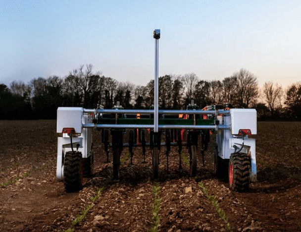
- industrial applications;
- electric vehicles;
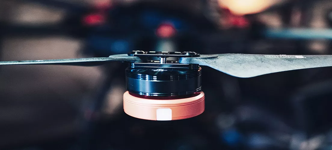
- unmanned aircraft systems;
- computer equipment;
- consumer electronics;
- robotics.
Thanks to the arrangement, BLDC motors can power small-sized yet high-performance devices which also expands their application area.

Of course, there are inexpensive low-power systems that do not need a programmable brushless DC motor controller with feedback. Here, the use of a BDC motor with a simple controller could make more sense. But if you still prioritize higher efficiency and durability over simplicity and cost-effectiveness, a brushless DC motor can be a viable option for your project.
Building a BLDC motor controller requires strong expertise in both electronic design and embedded software development. If implemented properly, a control unit can ensure the smooth operation of your motor and extend its lifespan. In the next section of this article, we’ll provide more details on how to design a brushless DC motor controller.
BLDC Motor Controller Circuit Design
A typical BLDC motor controller has a half-bridge or half-H bridge circuit. Unlike an H bridge, this circuit configuration has only two switches - one high-side and one low-side transistor.
Most brushless motors use two or three-phase power systems. So in a BLDC motor controller circuit diagram, this will look like two or three half-bridges (depending on the number of phases) with a pair of switches each.
Let’s take a closer look at a 3 phase brushless DC motor controller with Hall-effect sensors to view the basic principles of its circuit design.

The stator has three-phase windings located at 120° to one another. Each winding has a vector representation of voltage and current applied to the stator.
The BLDC motor controller Hall sensors identify the rotor’s position. Upon receiving the sensor data, the power MOSFETs switch the current, injecting it into the right winding. In a high power brushless DC motor controller, IGBTs and GaN switches can replace MOSFETs.
Either integrated or discrete gate drivers can control the transistors. The drivers of a brushless motor controller schematic act as intermediaries between the switches and a microcontroller (MCU).
The three-phase BLDC motor controller circuit includes six steps necessary to complete a full switching cycle (that is to energize all the three windings of the stator). By turning the high-side and low-side transistors on and off, the current flows through the stator windings in sequence.
When designing a BLDC motor controller, engineers can use different current switching, including trapezoidal and sinusoidal commutation. The names relate to the signal waveforms.
The trapezoidal commutation allows two windings out of three to stay energized simultaneously. In the sinusoidal approach, the phase shift complies with the law of sines, so current switching between the phases becomes smoother.
The trapezoidal method is simpler, but at low speeds, it tends to cause vibration in the motor. The sinusoidal commutation, on the other hand, becomes challenging at high speeds.
Typically, a sinusoidal brushless motor controller circuit uses pulse-width modulation (PWM). It helps regulate the current injected into the rotor’s windings and run the commutation process more smoothly and efficiently. This applies especially to closed-loop controllers that get feedback on the output signal and adjust the input power by varying the duty cycle.
A duty cycle is the percentage between the current pulse and the complete cycle of the current signal. A BLDC motor speed controller changes PWM duty cycles to create sinusoidal signals.

PWM switching frequency can be different for various applications. Although it should be high enough to prevent power loss. The physical limitations of the stator determine the maximum frequency level. However, there are also the specifications of the control unit itself.
So even if the stator allows you to increase the PWM frequency, you will not be able to do that because of the limited capabilities of your DC brushless motor controller.
As an option, you can employ hysteresis to control the operation of a BLDC motor. This method relates to the sinusoidal commutation too. It allows you to establish the upper and lower limits of the current supplied to the motor. As soon as the current reaches its upper or lower range, the transistor switches turn off or on respectively and change the average current using the law of sines.
You can implement a BLDC motor controller half-bridge as either an integrated circuit (IC) or as discrete components. This is one of the most common dilemmas you might face as you start figuring out how to design a BLDC motor controller.
A discrete circuit can be less reliable since the components should be assembled and soldered onto the board separately. A brushless DC motor controller IC has a smaller size, low production costs, and simplifies the design process. However, integrated circuits have power limitations. Above that, the failure of one component will lead to the replacement of the entire BLDC motor controller IC, not just this component.
Challenges of Making a BLDC Motor Speed Controller
Building a brushless DC motor controller circuit, you might come across some challenges. Depending on the motor’s functionality and application, you’ll need to choose suitable hardware and implement the required algorithms.
For example, BLDC motor controllers used in power electronics deal with high current and voltage. They require a high switching frequency. Here, it will make sense to use discrete components, including external high power transistors, such as IGBT and GaN.
One of the most challenging tasks when designing a brushless motor controller is to provide the rotor’s positioning accuracy. It can be done with sensors or with sensorless measurements.
Using position sensors is a simple approach that doesn’t require complicated control algorithms. But adding sensors to the design complicates the arrangement and maintenance of the motor.
Using the sensorless approach based on measuring back EMF simplifies the design of the brushless DC motor controller and makes the bill of materials (BOM) cheaper. The major challenge here is to make the rotor move first, since back EMF will not appear when the rotor is at rest. Thus, the controller will not receive the required information.
In addition, back EMF is proportional to the rotor’s speed. So the positioning accuracy will decrease if you run the motor at low speeds.

To measure the back EMF correctly, think through your brushless DC motor controller schematic as well as its software. You need to install current and voltage converters, add noise filters, and build digital signal processing (DSP) algorithms.
Nevertheless, a lot depends on the particular implementation of the measuring method. To achieve improved accuracy, you can combine different techniques.
For example, you can use an optical sensor or a rotary encoder together with a Hall-effect sensor. To detect the rotor’s position, you can also measure the back EMF and additionally receive data from a Hall-effect or laser position sensor mounted on the motor.
The main programming challenges in a BLDC motor controller design lie in the microcontroller’s firmware development. It involves commutation, detection of the rotor’s position, generation of PWM signals, and other functions.
Some microcontroller manufacturers offer embedded software tools that can help you write custom firmware for your motor controller’s MCU. For example, our partners from STMicroelectronics created the STM32 ecosystem for motor control that contains hardware and software development kits, firmware libraries, and other toolsets intended for the design of BLDC motor controllers.
The most common approach is to implement a proportional-integral-derivative (PID) algorithm in the MCU of a closed-loop motor controller. It is a simple, yet efficient solution for regulating the speed, torque, and other characteristics of the motor. For instance, a PID algorithm can measure the current speed, compare it with the setpoint, and change the frequency of the output signal accordingly. As a result, the speed of the motor will stabilize at the desired level.

In one of our projects, we created a BLDC motor controller circuit design for a bespoke gear drive. Our major tasks included the detection of the rotor’s position and regulation of the rotational speed with high accuracy.
Using a rotary encoder assisted with the positioning task, but the speed control became a challenge. The difficulty occurred because of the low resolution of the MCU peripherals, namely the timer that generated PWM signals. To solve this task, we implemented a custom PID algorithm to compensate for the limited range of bits.
Conclusion
Brushless DC motors have been in use for over fifty years. Their application area ranges from a small-sized consumer device to a complicated industrial automation system. The all-electronic control system increases torque, improves wide-range speed regulation, and enhances other characteristics of the motor.
Despite the reliability and high efficiency, such motors are not universal. First of all, they have a high price and a complex controller’s implementation. Thus, for some projects, a brushed DC motor controller could become a reasonable option.
One of the key design challenges of a BLDC motor controller lies in determining the position of the rotor. You can accomplish this in different ways, such as:
- using a suitable sensing device;
- measuring back electromotive force created in the stator’s windings;
- combining various methods to achieve the desired result.
Design of brushless DC motor controls can take resources and require unconventional engineering solutions at both hardware and software levels. If you need professional services or advice on how to make your own BLDC motor controller, feel free to contact us with your queries. We are ready to share our relevant experience in electronic design and firmware development.
Related
materials

All You Must Know About DC-DC Converters in Infographics
Read these infographics to learn how different types of DC-DC converters work, where they are used, and what problems one...
LEARN MORE 
LEARN MORE

DC-to-DC Converters: Functions, Common Types & Design Principles, Applications, and Challenges
Different sub-circuits in a device often require different voltages. When there’s only one power source, DC-to-DC converters are used to...
LEARN MORE
LEARN MORE
DC Motor Controller Design
A multi-mode motor controller for robots. Its functions include start and stop, speed regulation, differential steering, and smooth acceleration.
LEARN MORE
LEARN MORE