

DC-to-DC Converters: Functions, Common Types & Design Principles, Applications, and Challenges


- What are DC-DC converters and their functions?
- Common Types of DC-DC Converters
- Linear & Switching DC-DC Converters
- Non-Isolated & Isolated DC-DC Converters
- Step-down DC-DC Converters
- Step-up DC-DC Converters
- Universal DC-to-DC Converters
- Inverting DC-to-DC Converters
- Essential Characteristics of DC-to-DC Converters
- Common Issues Related to DC-DC Converters
- EMC Issues
- Safety Issues
- Thermal Considerations
- Developing Firmware for DC-DC Converters
- Conclusion
DC-DC converters can be found in almost any modern electronics. The applications of DC-DC converters range from smartphones and laptops to industrial and military systems. From this article, you can learn about their common types, their advantages and drawbacks, how they work, where and why they are used, and what issues one can face when designing electronics with DC-DC power converters.
- What are DC-DC converters and their functions?
- Common Types of DC-DC Converters
- Linear & Switching DC-DC Converters
- Non-Isolated & Isolated DC-DC Converters
- Step-down DC-DC Converters
- Step-up DC-DC Converters
- Universal DC-to-DC Converters
- Inverting DC-to-DC Converters
- Essential Characteristics of DC-to-DC Converters
- Common Issues Related to DC-DC Converters
- EMC Issues
- Safety Issues
- Thermal Considerations
- Developing Firmware for DC-DC Converters
- Conclusion
What are DC-DC converters and their functions?
DC-to-DC converters are electromechanical devices or electronic circuits that convert one direct current voltage or current level to another. In most cases, devices use only one power source. However, if different sub-circuits require different voltages to work properly, one needs to convert the input voltage to a lower or higher level. That can be done with DC-DC converters. Additionally, they stabilize voltages, not letting them drop or rise too much. For example, one of the purposes of car DC-DC converters is to regulate the voltage fluctuations in automotive alternators.

These circuits help distribute and manage power properly to provide each power consumer with appropriate voltage or current level. It also protects highly-sensitive sub-circuits. On top of that, in portable devices, they can raise voltage when the batteries are partially lowered, making power consumption more efficient. Such converters are used in many electronic devices. According to EMR’s Global DC-DC Converter Market report, more than half of them are used in smartphones, but they have other applications as well: from consumer electronics and telecommunication equipment to industrial and medical equipment, factory automation, transportation, robotics, power electronics, etc. As an electronics developer, we also make full use of various DC-to-DC converters when designing power electronics, hardware, and robotics.
Common Types of DC-DC Converters
Linear & Switching DC-DC Converters
Linear converters reduce output voltage with a resistive load. In a typical circuit of this type, the input and output are connected with a transistor (RVT1 in the picture below). The input voltage is reduced by the voltage across the transistor, which causes the output voltage to drop.

Such circuits are quite simple and cheap but have a number of serious drawbacks. They can only be used to decrease voltage. Moreover, their efficiency drops as the difference between the input and output voltage rises. As long as the device isn’t powered by batteries, this drop is irrelevant. On the other hand, this unused power dissipates as heat, and such models overheat easily if the input and output voltages differ greatly.
Nevertheless, they are used in low-power devices and nodes that require high-quality output voltage and low output voltage ripple, or in devices that are sensitive to electromagnetic interference. They are simple in design, use few components, and can save a lot of space (unless there’s a need to use a heat sink). Linear converters are typically used in audio and video electronics, communication equipment, medical and measurement devices.
Switching converters use a switching element that charges a storage capacitor with electrical pulses. This voltage is then smoothed with the capacitor and transferred to the load. The output voltage level is defined by the duty cycle of the switching element.

Their efficiency is much higher, compared to linear converters, and can reach 85-90%. That is why engineers prefer using them in battery-powered devices. Since they’re more efficient, they do not generate as much heat and can be used to decrease and increase the output voltage. Therefore, they are used whenever linear types are not an option. On the other hand, they generate more electromagnetic noise and require more components, which makes them more expensive.
In one of our projects, we needed to power several sub-circuits in a device with a number of radio transmitters. The sub-circuits required 5V, while the input voltage was 12V. The maximum electric current was expected to reach 2A. In this case, using a linear converter would be impractical because more than half of the energy would be dissipated as heat (up to 14W at full power). Mounting a cooling radiator wasn’t an option either, since the case was too small (10x10x1 cm). Instead, it was decided to use a TPS54335 switching converter.

As you can see, both these converter types have their own pros and cons, so it can be a tough call. When deciding which converter to use, one has to take into account a range of factors, including potential issues related to electromagnetic compatibility, efficiency, overheating, etc. That’s why you need a team of experienced professionals to do the job. Don’t hesitate to contact us to discuss your project or ideas.
Non-Isolated & Isolated DC-DC Converters

Non-isolated DC-DC converter design features a direct connection between the input and output circuits (i.e. have a single circuit). They are used in low-power devices to benefit from their relatively low cost, smaller size, and higher efficiency compared to isolated models, as there is no transformer where energy would be lost. Such types are used in communications, computer, automotive, and other industries.
In isolated converters, the input and output are separated from each other (typically with a transformer). It prevents direct current flow between the two circuits. Often, the primary and secondary circuits are separated for safety, which is why this design is widely used in high-voltage DC-DC converters. Also, this design allows you to break up ground loops to protect sensitive circuits from noise.
They are used in programmable logic controllers, industrial automation, as power supplies for IGBT drivers, etc. Particularly, non-isolated DC-DC converters may not be allowed in devices due to safety concerns. For example, one of the systems Integra Sources helped develop was supposed to work in a humid environment. So, using an isolated converter was a must. In this particular case, we used an LM25017 fly-buck regulator:

Step-down DC-DC Converters
Also called buck converters and choppers, they produce lower output voltage, compared to input.
In a simple buck converter, the switching element (K) rapidly turns the power on and off. The output voltage looks like a series of square waves. While the switch is on, the coil (L) and the capacitor (C) accumulate the energy. The capacitor also smoothes these waves into a DC voltage. When the voltage reaches the required level, the switching element is turned off and the diode (D) is turned on. The self-induced emf makes the current flow through the diode. The energy accumulated in the coil charges the load.

Step-down DC-to-DC converters are used in many spheres, including battery chargers, multimedia players, game consoles, monitors, and television sets.
Step-up DC-DC Converters
Also called DC-DC boost converters, they can produce voltage higher than the input voltage. In a typical boost converter, the induction coil receives almost all the current, while the closed diode doesn’t let the current charge the capacitor and the load. Due to a higher electric current, the coil accumulates much more magnetic field energy compared to a step-down schematic. When the voltage drops to a certain point, the power key is turned off, while the diode is turned on. The input voltage adds to the energy stored in the coil, which makes the output voltage of boost DC-DC converters higher than the input voltage.

Boost converters are used whenever you can’t provide a high enough input voltage with batteries or there’s simply not enough room for more batteries. They are typically used in hybrid vehicles, lighting systems that use energy-saving lamps, portable lighting devices, etc.
Universal DC-to-DC Converters
They can increase and reduce the input voltage to produce a higher or lower output level. They are also called buck-boost converters. This type is often used when you deal with a wide input voltage range. For example, it’s typical for car batteries.

Such circuits are often used in devices powered by Li-ion batteries. A universal converter lowers the voltage to the required level. But as the battery’s voltage drops with time, it starts raising it. They can also be found in measuring equipment, photo and video cameras, MP3 players, GPS systems, wireless devices (keyboards, mice, transmitters), LED lighting, etc.
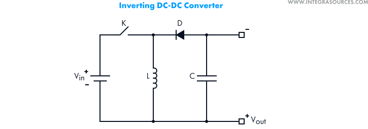
Inverting DC-to-DC Converters
Their primary function is to invert the polarity of the output voltage. The output level can be higher or lower than the input level. Such models are very useful when the device requires a dual supply (for example, operational amplifiers).
Essential Characteristics of DC-to-DC Converters
When choosing DC-to-DC converters for a device, engineers pay attention to different characteristics and parameters, with the most important ones being the following:
- Input voltage
This parameter is defined by the power source used. Different power sources (for instance, AC-to-DC adapters or batteries) provide different input voltages. When designing electronics, a hardware development company must make sure the DC-DC converter can withstand these voltages.
- Output voltage
DC-DC converters can produce either fixed or adjustable output voltage. The latter can vary from a minimum to a maximum value. In both cases, the choice of models is defined by the voltage range required by the load.
- Output current
Output current (along with the output voltage) defines the electrical power that a converter can provide.
- Efficiency
Efficiency is the percentage of the input power delivered to the output. It can be calculated with the following formula:

As mentioned above, the efficiency of DC-DC converters can vary a lot. In some cases, this parameter is considered crucial. For example, if the device is powered by batteries, the efficiency defines how long the device can work before you have to replace them.
In some cases, efficiency itself is not as important. However, the energy lost during conversion dissipates as heat. This in turn can lead to undesirable consequences.
- Temperature
Since extra energy goes into heat, overheating can become a serious issue. This problem can be partially solved with proper casing. But in certain cases, one may have to use additional thermal protection.
- Size and mounting types
DC-DC converters are available in many package types. If it needs to be mounted into a PCB, designers can choose from a variety of mounting styles, including surface or through-hole mounting, single in-line or dual in-line pin. The size also matters when engineers develop small devices.
- Stable supply
And finally, when picking converters for a device, it’s also important to make sure the manufacturer will not stop supporting the model in the near future. That’s why our team always gives priority to the latest models.
Common Issues Related to DC-DC Converters
Another common problem for any electronics design company is meeting various regulatory and certification requirements. Using DC-DC converters can affect the device’s characteristics and features from the safety and electromagnetic compatibility perspectives. Furthermore, different applications can impose additional requirements.
For example, replacing a switching converter with a cheaper linear one may require a cooling system. But such a system may turn out to be even more expensive. Solving such problems is Integra Source’s job, so if you have a product idea and need a consultation, feel free to contact us directly and ask any questions.
EMC Issues
Electromagnetic compatibility is one of the most obvious issues one may face when using DC-DC converters. Due to higher efficiency, switching types are very popular. However, as mentioned above, they generate electromagnetic noise.
Therefore, such devices must be tested for electromagnetic compatibility to make sure they don’t cause electromagnetic interference effects on other devices. You can read more about EMC testing in the article on common consumer electronics certifications.
These issues are generally solved with proper PCB layer stackup, additional capacitors, and filter circuits. Thorough PCB testing is usually required to achieve the best result. For example, designers must avoid mounting converters (and especially the conductor coil) near sensitive components and sub-circuits. On the schematic below, you can see an inductor (L1), as well as four ceramic capacitors (C5-8) and one electrochemical capacitor (C4). They are all mounted there to protect an analog sub-circuit from EM interference. The ceramic capacitors suppress the high-frequency noise from the converter, while the electrochemical capacitor smoothes low-frequency fluctuations from different sources. This combination considerably improves the quality of the power supply.

Safety Issues
In many devices, the difference between the input and output voltages can reach hundreds of volts, which can be extremely dangerous. Therefore, equipment using high-voltage (HV) DC-DC converters (for instance, medical electronics) must meet safety requirements. They are regulated by different standards, with the most common being IEC 60950-1 for Information technology equipment, IEC 60335-1 for electrical appliances for household and similar purposes, and IEC 60601-1 for medical electrical equipment. Note that national standards are based on International Electrotechnical Commission’s standards but may contain deviations.
Whenever it is necessary to provide the required safety level, electronics designers use isolated converters, as they don’t have a direct connection between the input and output circuits. The IEC 60950-1 standard distinguishes five electrical insulation grades.
- Functional Insulation
The functional insulation between the input and output circuits is only required for the proper work of the device. However, it does not provide enough protection from electric shock if the input-to-output insulation suffers a breakdown or fault. This level of protection must meet at least one of the standard’s requirements sets:
a) Clearance and creepage distances;
b) Electrical strength tests;
c) Fault condition testing.
A device’s DC-DC converter is allowed to have functional insulation if:
- The AC-to-DC power supply uses reinforced or double insulation between the AC input and DC output.
- The AC-to-DC power supply uses basic or supplementary insulation, while the secondary circuit of the DC-DC converter connects to protective Earth.
- The AC-DC supply has basic or supplementary insulation, while the primary circuit of the DC-DC converter connects to protective Earth.
- Basic Insulation
This insulation grade provides basic protection against electric shock. Devices must meet all three (a, b, and c) sets of requirements. This level is required if the AC-to-DC power supply has functional insulation between the AC input and DC output, while the secondary circuit of the DC-DC converter connects to protective Earth.
- Supplementary Insulation
Apart from meeting the basic insulation requirements, this grade adds one more level of protection, such as increasing the distance through insulation by 0.4 mm for peak voltages above 71V. This level of protection is required if the AC-DC power supply uses basic insulation between the AC input and DC output.
- Double Insulation
This protection level combines basic and supplementary insulations.
- Reinforced Insulation
It’s a single insulation system capable of providing the same protection grade as double insulation. It can comprise several protection layers and is required if the AC-DC power supply has no insulation or functional insulation between the AC input and DC output.
Thermal Considerations
DC-DC converters are primarily used in portable devices. Mobile environments can be extremely harsh on electronics, so developers must take care of heat generation issues as early in the design stages as possible.
Note that a DC-DC converter’s maximum full-power temperature can be very different from the temperature at which different standards (particularly, EN60950-1 and UL60950-1) begin to derate the device that uses this converter.
Most heat is generated by transformers. Therefore, thermal insulating systems are rated by standards according to what materials they are made from and how they interact at high temperatures. In most DC-DC converters, you will find planar transformers that are constructed within the main PCB. They are not regarded as safety hazards unless their temperatures exceed the maximum rating of the PWB (printed wiring board).
In rare cases, when transformers use unapproved (class A) thermal insulating systems, they are regarded as safety hazards when their internal temperatures exceed +105°C. But in most cases, such converters will require transformers with recognized thermal insulating systems – Class B that can withstand operating temperatures of up to + 130°C and class F that can withstand +155°C.
Overheating issues can be solved with a combination of methods. For example, in the picture below, you can see four power converters that generate a lot of heat. To solve the issue, our team used MOSFET transistors with a lower static drain-to-source on-resistance. It means that less energy is converted into heat. Additionally, we made wide parallel traces (going through all four layers of the PCB) and added as many vias as possible. It allows the heat to be dissipated from both sides of the board.

Developing Firmware for DC-DC Converters
Time is always a critical factor for these circuits. Changing the voltage level too early or too late can result in the inefficient performance of the device or even malfunctions. In most converters, everything is controlled by hardware, and response time takes no longer than microseconds. Analog DC-DC converters modules are simple but perform well enough.
However, in some cases, electronics development companies may decide to use microcontrollers in the design of DC-to-DC converters.
When there’s a need to control many parameters (in complex battery management systems, for instance), this function can be implemented with a microcontroller. It provides better flexibility in the realization of control algorithms. For example, in inverter welding machines, you need to control the power keys and the output voltage and also measure the output current. The device has different operating modes, including the one designed for working under the conditions of increased humidity. This mode requires reducing the output voltage to not exceed 30 V.
In such cases, the control functions can be handed over to a microcontroller. Microcontrollers fulfill the following functions:
1. House-keeping to ensure proper work of a DC-DC converter.
2. Parameter setting that implies dynamic control over the output voltage or current, etc.
3. Generating control signals for transistors.
In such converters, almost all functions are managed through code. Therefore, it’s very important to properly organize the firmware structure and thus provide the highest speed possible. The microcontroller’s tasks can be divided into two types: time-critical, such as loop control, ADC measurements, system protection, state machine; and non-time-critical, such as fault logging, PMBus or universal asynchronous receiver/transmitter communication, etc.
Thus, the firmware can also be divided into two parts: one that takes care of time-critical tasks (the interrupt loop) and one that controls non-time-critical tasks (the background loop).

After the system is initialized, the central processing unit goes into an infinite loop where non-time-critical tasks are carried out. The timer here is responsible for generating fixed-frequency interrupts. When an interrupt occurs, the CPU stops performing its current task to store related data and then jumps to the interrupt routine. After completing the interrupt routine, the CPU resumes the background loop.
The goal of the interrupt loop is to control the converter, measure the ADC inputs and protect the system. It is crucial here to know the current state of the converter, as well as its current and upcoming tasks. For that purpose, the interrupt loop uses a state machine as its key part.

The central processing unit monitors the input voltage until it exceeds a pre-defined threshold. This activates the converter that performs a soft start to increase the output voltage up to a certain point. Then it switches to regulation mode. The converter stays in this mode until a fault occurs (in which case, it will shut down and latch or restart if commanded to) or it is commanded to turn off.
Conclusion
Most modern devices use distributed power architecture. Instead of using multiple power sources, developers now use a single power supply that is distributed between various points of need with DC-DC converters. They are especially useful for designing portable devices since their efficiency and run time are limited by the number of batteries and their voltages.
When designing electronics, developers must choose from various DC-to-DC converter types that can meet technical specifications, efficiency requirements, as well as EMI and safety standards. A single device can contain multiple converters of different types that supply a number of sub-circuits. So, it’s a challenging task to find models suitable from technical and financial perspectives.
This is one of the many issues electronics developers face when designing new products and systems. Thanks to our rich experience, the Integra Sources team can handle any task from designing printed circuit boards to developing electronic products and power electronics. Contact our team directly to discuss your project.
View an infographic variant of our post about DC-DC conventers.
Related
materials

All You Must Know About DC-DC Converters in Infographics
Read these infographics to learn how different types of DC-DC converters work, where they are used, and what problems one...
LEARN MORE 
LEARN MORE

DC Motor Controller Design
A multi-mode motor controller for robots. Its functions include start and stop, speed regulation, differential steering, and smooth acceleration.
LEARN MORE
LEARN MORE

DC Motor Controller: What It Is, Design Principles & Circuit Examples
Supported by our own experience, this article provides an introduction to the control systems of DC motors. You will find...
LEARN MORE
LEARN MORE