

DC Motor Controller: What It Is, Design Principles & Circuit Examples


- Introduction
- What Is a DC Motor Controller?
- Types of DC Motor Controllers
- DC Motor Type
- Type of Power Regulation
- Motor Power
- Motor’s Operating Voltage
- Type of Control Signal
- Type of Control
- Application Area of DC Motors and Controllers
- BDC Motor Controller Circuit Design
- Challenges of Making a BDC Motor Controller
- Conclusion
You can find a DC motor in many electronic appliances around you, including in an electric toothbrush, a washing machine, a printer, and a car. A motor controller ensures the efficient and safe operation of the motors used in these appliances. In this article, you will learn about the working principles and applications of this electronic device. We’ll tell you about the design nuances of a control unit used in one of the most popular electrical motor types – a brushed DC motor.
- Introduction
- What Is a DC Motor Controller?
- Types of DC Motor Controllers
- DC Motor Type
- Type of Power Regulation
- Motor Power
- Motor’s Operating Voltage
- Type of Control Signal
- Type of Control
- Application Area of DC Motors and Controllers
- BDC Motor Controller Circuit Design
- Challenges of Making a BDC Motor Controller
- Conclusion
Introduction
A direct current (DC) motor is the oldest type of electrical motor that has gained widespread use in a variety of electronic devices and equipment. DC motors have different arrangements and operation peculiarities.
The common feature and the essential condition of all DC motors is the generation of a variable magnetic field that provides their non-stop operation. In an alternating current (AC) motor, a magnetic field changes polarity on its own.
A DC motor has some significant advantages, and one of them is the simplicity of its control system. Here, we’ll tell you how a DC motor controller works and how you can use it. In addition, we’ll share our personal experience and brief you on the design and challenges that you can meet while building your own controller.
In this article, we have focused mainly on brushed DC (BDC) motor controllers. To learn more about a BLDC motor controller, its design, and working principles, you can check a related article on our blog.
What Is a DC Motor Controller?
The intended use of a motor controller is to manage the performance of an electrical motor. Irrespective of the motor type, this electronic device can fulfill the following functions:
- start/stop the motor;
- change the rotation direction;
- control the speed and torque;
- provide overload protection;
- prevent electrical faults.
DC motor controllers may have different specifics defined by their type (brushed, brushless, stepper) and the device in which the motor is used. For instance, a DC motor controller for an industrial brushed motor uses different working principles and has a different design compared to a controller for DC motors in electric vehicles.
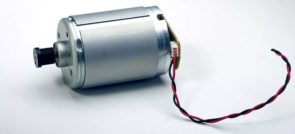
All direct-current motors must have two core elements: a stator and a rotor (armature), although critical functions can be performed by other components as well. A brushed DC motor comprises the following units:
- a stator with windings or permanent magnets;
- an armature, or rotor, with windings;
- a commutator, or collector, with brushes connecting the armature with a DC power supply.
When applied to the rotor, the electric current generates an electromagnetic field and makes the armature rotate. The similar poles of the field around the stator and rotor repel each other, which causes a unidirectional motion.
As soon as the opposite poles meet, the commutator switches the current supplied to the armature. This creates the reverse polarity of the magnetic field, and the armature keeps rotating.

A controller of a brushed DC motor manages the speed and torque of the motor by regulating the current and voltage injected into it. The major design and working principles of BDC motor controllers can differ between their types.
Types of DC Motor Controllers
There are different types of DC motor controllers along with the principles of their classification. The infographic below shows this variety.

DC Motor Type
First, controllers vary according to the type of DC motor. For example, unlike a brushed DC motor, a brushless DC (BLDC) motor has an electronic commutator without brushes. It has a rotor with permanent magnets and a stator with windings.
A brushless DC motor controller uses sensors to specify the rotor’s position. It switches the current in the windings with the help of transistors. In our article dedicated to a BLDC motor controller, we provide a detailed description of its working principles and design features.
A stepper motor belongs to the group of brushless DC motors, but its distinguishing feature is that it rotates in stages or steps. After each step, the rotor stops at a certain angle. It allows the device powered by this motor to shift and fix positions with high precision. A stepper motor controller provides current in pulses, energizing poles of the stator and making the rotor move.
The other classifications are typical of almost any electrical motor’s controller. Let’s briefly go over them through the example of a brushed DC motor controller.
Type of Power Regulation
In a BDC motor controller, the speed and torque are regulated by changing the power supply with the help of voltage regulators. They can be either a separate system or a part of the controller. For different purposes, engineers can use linear or switching regulators.
A linear regulator keeps the output voltage at a constant level with a resistive load. The output is stable no matter what input voltage is supplied by the power source. In a switching regulator, the output is stabilized through pulse-width modulation (PWM). You can read more about linear and switching regulators in our article on DC-DC converters.
A PWM DC motor controller can supply voltage in pulses, changing the ratio of the pulse to the pulse period which is called the duty cycle. By adjusting duty cycles, you can control the motor speed. A switching regulator has higher efficiency and less power loss, and PWM is widely used in speed controller design for DC motors.
Motor Power
Motor power relies on the current supplied by the power source. Thus, a low-power BDC motor needs a low current controller and vice versa. A high current DC motor controller typically uses a switching regulator.
Motor’s Operating Voltage
Depending on the voltage necessary for the motor’s operation, you can choose a low or high voltage controller. A switching regulator works well for controllers with a wide operating voltage range. A linear regulator better suits a low voltage DC motor controller because the excessive input voltage may cause power loss and even thermal overload.
Type of Control Signal
Controllers are classified into digital and analog versions. The main difference between a digital DC motor controller and its analog variant is that the former comprises microcontroller (MCU) based hardware and firmware.
Type of Control
Controllers that receive no feedback from the motor are called open-loop, or non-feedback, controllers. They operate blindly, so to speak, as they cannot detect the results of their commands. That’s why such controllers are used in simple systems that don’t require automatic control.
Controllers that do receive feedback from the motor are called closed-loop, or feedback, controllers. They can detect deviations from the desired values and correct the control signal accordingly. To maintain a process parameter at a desired level, engineers often use the PID mechanism in feedback control loops.
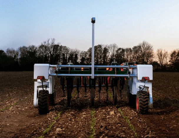
Open-loop and closed-loop systems are fundamental concepts of control theory. Depending on the requirements or complexity of the electronic device, you can implement a control system either with or without feedback. For example, a stepper motor can operate with an open-loop controller. A servo DC motor controller, used for accurate positioning in high-performance applications, is a closed-loop system.

The picture above shows examples of closed-loop and open-loop control systems. In the first case, the robot’s motor controller receives feedback and regulates the speed in accordance with the landscape conditions. In the case of the non-feedback system, the motor controller gets no feedback. So, the robot’s speed decreases as it reaches a plateau.
Application Area of DC Motors and Controllers
DC motors may find use in different devices and systems depending on their characteristics. Thus, stepper and servo motors power machines that require precision positioning such as:
- robots;
- printers;
- cameras;
- CNC machines.
In addition to closed-loop control, advanced DC servo motors with a variable speed DC motor controller show high performance and reliability in complex industrial applications.
The absence of brushes, which are wear-prone parts, makes BLDC motors more durable. Apart from that, the electronic commutator doesn’t make sparks and reduces electromagnetic interference (EMI). So these motors are widely applied in electric vehicles, heating, and ventilation systems because of their reliability. You can learn more about the construction and application of brushless motors in our article on a BLDC motor controller.
Brushed DC motors have been in use for about two hundred years. Although more recent technologies have partially replaced them, they are still popular in different industries and applications.
BDC motors may have a very simple design and are easy to control (some of them may not even need a controller). This is a cost-effective solution that can perfectly fit low voltage devices powered by lithium-ion batteries, including robotics and consumer electronics.
Building an autonomous robotic lawn mower, we installed a reversible DC motor controller with a PWM switching regulator for a brushed DC motor chosen by the customer. The idea was to develop a low power consumption and budget-friendly system.
The robot could easily move in any direction, avoid obstacles, make stops, and move again immediately. We achieved this by using a pulse width modulation DC motor controller that regulated the speed and rotational direction of the motor.

Accessibility and simple implementation of BDC motors and their controllers make them a suitable solution for a number of projects. In this article, we’d like to share our own experience in the design and implementation of a brush DC motor controller. You’ll also learn about challenges you can meet if you decide to build it yourself.
BDC Motor Controller Circuit Design
A traditional BDC motor controller circuit is an H-bridge. This is an electronic circuit with four open/close switches that supply positive and negative voltage by turns. By closing high-side and low-side switches in a diagonal pattern, the motor rotates in one direction. The rotational direction will change as soon as these switches are open and the opposite switches are closed.
If you need a motor with a unidirectional rotation, you can build a BDC motor controller using a simpler circuit with only one open/close switch. Choosing a transistor switch, make sure it meets the required parameters of the motor, for example, the maximum current. Otherwise, the transistor will burn out.
Compliance with the system requirements is the basic principle you should follow while selecting components for your DC motor controller schematic. This relates to an MCU, gate drivers necessary to control the transistors, and other components.
You can use either an integrated circuit (IC) or discrete components. From a developer’s point of view, a DC motor controller IC is a simpler and more convenient solution. With a discrete circuit, it will take you the time and effort to assemble and solder the components. The design of an integrated circuit, however, is quite expensive, and it can earn its keep only in case of mass production.
An integrated H-bridge driver is a circuit with built-in power transistors. Despite the simplicity and reliability of its design, the gate driver IC is intended for low-voltage and low-power applications. Additionally, such gate drivers are not interchangeable. If they become discontinued, you’ll have to redesign the schematic together with the printed circuit board.

BDC motor controller circuit design depends on the type of signal, power regulation, control system, and other features. You can choose among various options based on your technical specifications and budget limits.
Cooperating with Basicmicro Motion Control, we created brushed BDC motor controllers for DIY robot kits. It was a variable DC motor controller with a switching voltage regulator. An important feature of the controller is that it can use both an open-loop and a closed-loop system.
With the help of our 2-channel BDC motor controllers, users can control robots remotely via a wireless communication module. Our team provided electronic design and embedded software development for the project.

We used an H-bridge circuit for the controllers. As it was a discrete circuit, Integra’s engineers had to choose MCUs and gate drivers with separate semiconductor switches. We opted for power MOSFETs that fit well with low voltage controllers because of the following advantages:
- a fast switching speed;
- a low price;
- easy maintenance;
- high efficiency.
Designing a high current DC motor controller schematic, we used an IGBT that combines features of power MOSFETs and bipolar switches. It provides a high level of current and is well suited for complex power electronics systems.
Another option that you can choose for your project is a GaN transistor made of hard and extremely durable semiconductor material. It can resist high temperatures and operates at very high frequency and voltage ranges. GaNs are used in high-power electronics, industrial, and aerospace applications. However, their production cost is still very high, so it will raise the price of your circuit design as well.
As a result, we designed a programmable DC motor controller with several operation modes. It could be controlled with the help of analog and digital signals. In addition, it could use a closed-loop system and read data from a digital quadrature encoder installed on the rotor.

The encoder converted the rotational speed and direction of the motor into digital signals recognized by the controller. When changes occurred, the controller adjusted the control actions as necessary.
To provide safe operation of the motor, our developers implemented overcurrent, overvoltage, and overtemperature protection systems. To achieve this, we added the corresponding sensors in the DC motor controller design.
Challenges of Making a BDC Motor Controller
Building a BDC motor controller can be quite simple, but it still involves some challenges. These can relate to both circuit design and firmware development. Let’s take a look at the things that may need your special attention.
As we have mentioned earlier, switches are open and closed diagonally in an H-bridge circuit, but these actions can’t go on simultaneously. There will always be a moment when all the transistors are open. It may lead to voltage and power loss, or even short-out if the opposite upper and lower switches are in the on position.
To avoid this situation, you can introduce dead time. This is a short period of time when all switches of an H-bridge circuit are closed. Using dead time, you can make sure the upper switch will open only after the lower switch is closed.

PWM frequency (the number of pulse periods per second) is an important parameter that you should adjust in a proper way. The lower the frequency, the higher the power loss, and vice versa. However, in case the PWM frequency is too high, the MCU may have problems with generating PWM signals of the required value. In addition, the very high frequency may lead to the malfunction of the gate driver and transistor switches as they may not be compatible with it.
When writing firmware, remember to set up the correct PWM frequency to ensure the smooth operation of your motor controller.
As you deal with a brushed DC motor, you might come across the problem of excessive electromagnetic interference. Generated because of the constant switching of the commutator, it affects neighboring electronic components. To reduce it, you could implement different filters that protect the wires from EMI.
Designing BDC motor controllers for our robotics project, we had to meet some challenges.
The basic customer requirements included the wide operating voltage and current ranges. At that moment, there were no suitable off-the-shelf integrated gate drivers or GaN semiconductors. In addition, this range was too low for an IGBT. Thus, we had to search for a solution among discrete power MOSFETs.
Our team considered several circuit options and chose a standard gate driver with external MOSFETs. By implementing this discrete component solution, we simplified the schematic design and cut development costs. As a result, Integra’s engineers achieved stable operation of the BDC motor controller in the range of 6 up to 24 volts and up to 25 amps.
As soon as we used a discrete circuit, the responsibility for the major functions of the BDC motor controller rested with the MCU. Our engineers implemented algorithms that generated PWM signals with the required duty cycles and dead time.
Implementing a feedback control system, we faced a problem with the microcontroller that couldn’t process the encoder signal outputs. So we had to add a CPLD that could read high frequency signals. If you are planning to build a brushed DC motor controller with feedback, make sure your MCU can provide this opportunity.
Conclusion
A brushed DC motor is one of the most common types of electrical motors. It is widely used in consumer electronics, robotics, low-power industrial and automotive applications. A BDC motor, as well as its control system, has a simple construction and easy implementation.
With some viable alternatives available now, it’s becoming hard for a BDC motor to stay competitive in high-power electronics. Besides, its controller has brushes, and you will have to replace these wearable parts with time. However, with proper use and maintenance, it can provide an efficient and long-lasting performance.
If you need a controller for a BDC motor, you can use an off-the-shelf device that fully meets your requirements. Or you can build your own solution with a tailor-made circuit design and custom firmware. Electronics and semiconductor manufacturers offer a rich selection of hardware and software components that you can use in your project. For example, in building a BDC motor controller circuit for the robotic lawn mower, we used STM32F4, which is part of the STM32 ecosystem for motor control.
Entrusting your project to an external engineering team, make sure they have relevant skills and expertise. An experienced developer will consider each nuance and figure out how to design a DC motor controller for your particular project.
Integra has provided schematic design, PCB layout, and firmware development services for 250+ projects, including power converters, voltage regulators, and motor controls. During our 9+ years of experience, we have worked with a wide range of microcontrollers and semiconductor devices. We have created circuits for applications that operate over a full range of current, voltage, and switching frequency.
If you are planning to build a DC motor controller for an electric car, a robot, or a home appliance, drop us a line and get help with electronic design, firmware development, and related services.
Related
materials

All You Must Know About DC-DC Converters in Infographics
Read these infographics to learn how different types of DC-DC converters work, where they are used, and what problems one...
LEARN MORE 
LEARN MORE

DC-to-DC Converters: Functions, Common Types & Design Principles, Applications, and Challenges
Different sub-circuits in a device often require different voltages. When there’s only one power source, DC-to-DC converters are used to...
LEARN MORE
LEARN MORE
DC Motor Controller Design
A multi-mode motor controller for robots. Its functions include start and stop, speed regulation, differential steering, and smooth acceleration.
LEARN MORE
LEARN MORE